MSP430 GPIO
Input or Output
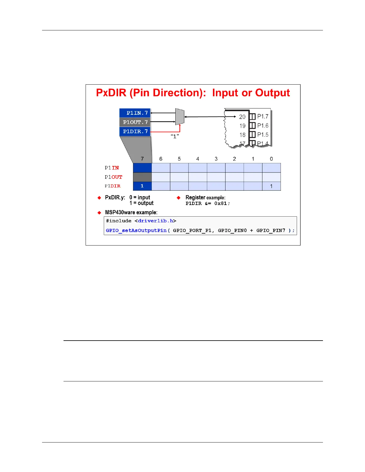
Each GPIO pin is individually controllable – that is, you can configure each pin to be either an
input or an output. This is managed via the DIR register; for example, to set P1.7 to be an output
you would need to set P1DIR.7 = 1 (as shown below).
Remember that we had multiple programming methodologies? Our graphic above shows us two
of them.
• You’ll see the “Register example” above uses C code to set the P1DIR register to a given hex
value.
• On the other hand, in the “MSP430ware example”, the DriverLib function allows you to set
one or more pins of a given port as an output. (By the way, to setup the pin as an input, you
would use the GPIO_setAsInputPin() function.)
Both methods will end up setting the same registers to the same bit values, though nowadays
most teams prefer the more intuitive coding of the DriverLib example. Why? Because you don’t
really even have to know the register details to understand that pins 0 and 7 are setup as outputs.
Note: As stated earlier in the chapter, the other two programming methods are discussed
elsewhere. The Energia method is discussed in its own chapter. Arduino has predefined
function names for setting I/O pins. Similarly, the GRACE tool is discussed in its own
chapter – which as of this writing is only found in the Value-Line Launchpad version of
this workshop.
With the direction configured you will either use the respective IN or OUT register to view or set
the pin value (as we’ll see on the next couple pages).
MSP430 Workshop - Using GPIO with MSP430ware 3 - 7