Lab 6a – Simple Timer Interrupt
Lab 6a – Simple Timer Interrupt
Similar to lab_05a_buttonInterrupt, we want to blink an LED based upon a timer. In this
case, though, we'll use TIMER_A to generate an interrupt. During the interrupt routine we'll toggle
the GPIO value that drives an LED on our Launchpad board.
As we write the ISR code, you should see that TIMER_A has two interrupts:
− One is dedicated to CCR0 (capture and compare register 0).
− The second handles all the other timer interrupts
This first TIMER_A lab will use the main timer/counter rollover interrupt (called TA0IFG). As with
our previous interrupt lab (with GPIO ports), this ISR should read the TimerA0 IV register (TA0IV)
and decipher the correct response using a switch/case statement.
Lab 6a Worksheet
Goal: Write a function setting up TimerA0 which generates an interrupt every two seconds.
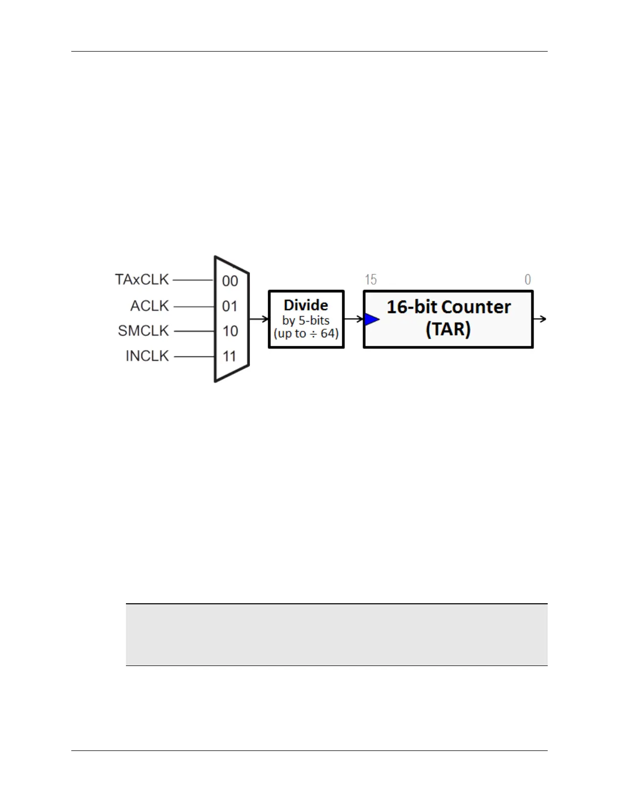
1. How many clock cycles does it take for the 16-bit TimerA0 to ‘rollover’? (Hint: 16-bit
timer)
________________________________________________________________________
2. If our goal is to generate a two second interrupt rate, what clock input and divider
value will get our timer near 2 seconds?
Clock input: ______________________________________________________________
Divide value: ______________________________________________________________
Hint: Since we are interested in 2 seconds, a slow clock might work best.
Another Hint: Look up the arguments for the TIMER_A_configureContinuousMode( )
function in the MSP430® Peripheral Driver Library User’s Guide.
MSP430 Workshop - Timers 6 - 37