Thermo Fisher Scientific Micro-Tech 9101/9201 Reference Manual, Rev J A-47
For more information, see “Appendix C—Communication Protocols.”
Installation
To install the COMM board(s), do the following.
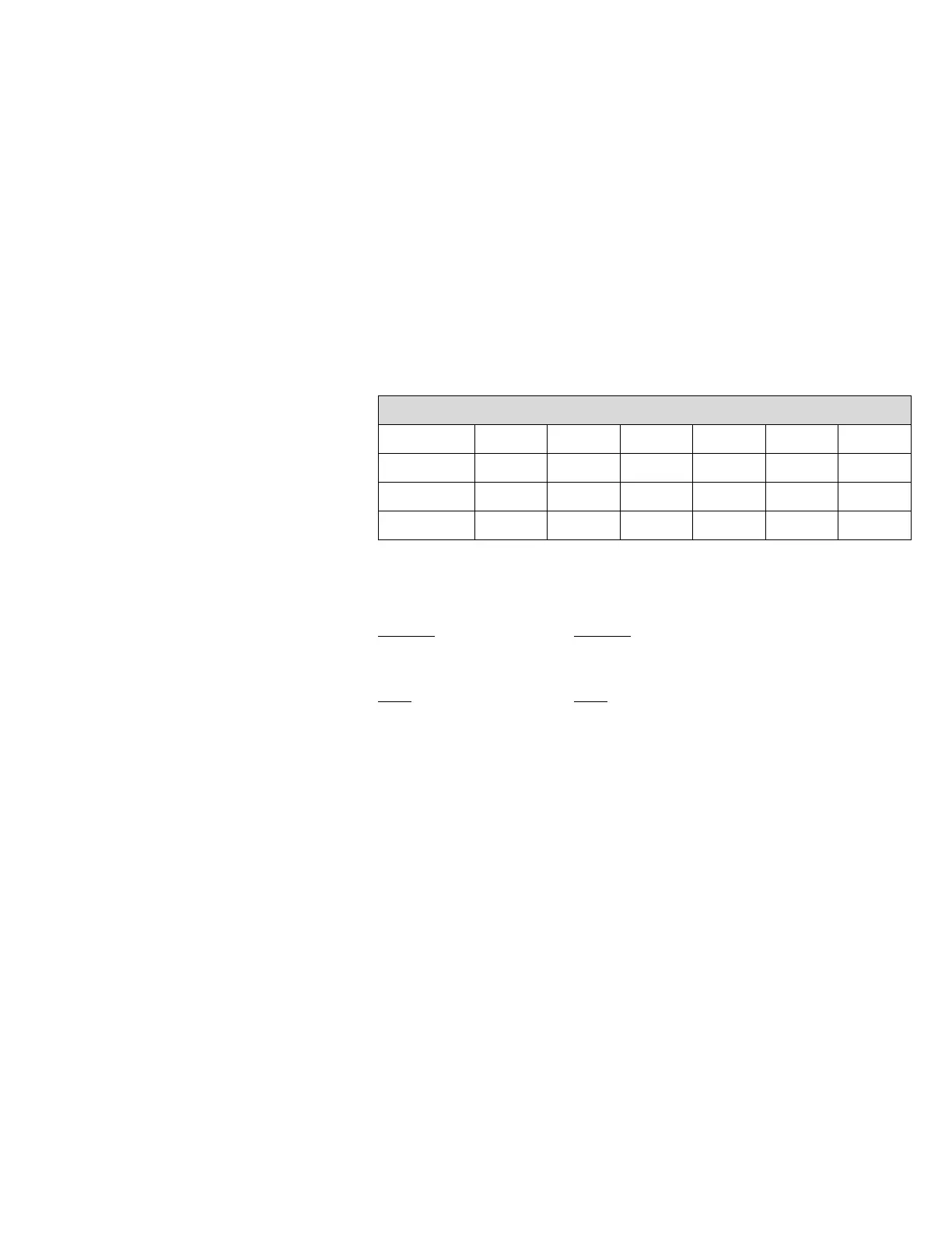
1. Select the jumper positions on the COMM board for the desired
communication standard. Below is a table which summarizes the
jumper positions for selection of the electrical interface. The jumper
locations are shown below.
Jumpers
Mode OP1 OP2 OP3 OP4 OP5 OP6
RS-232 “A” “A” “A” “A” “A” “B”
RS-485* “B” “A” “B” “B” “MDP” “TRM”
20 mA “B” “B” “A” “A” “A” “C”
* Default
“MDP” “TRM”
For RS-485 only For RS-485 only
OP5 OP6
“A” Normal “A” Terminated
“B” Multi-drop “B” Not terminated
2. Open the Micro-Tech wall mount enclosure and turn power off at the
mains, or remove panel mount enclosure from the panel and remove
top cover allowing access to the motherboard.
3. Remove the field mating connector. Wire the connector per the
supplied field-wiring diagram at the end of the manual.
4. Remove the hex head mounting screw from the connector end of the
COMM board.
 Loading...