Initializing the Micro-Tech
Initializing the Software
2-34 Micro-Tech 9101/9201 Reference Manual, Rev J Thermo Fisher Scientific
The idler spacing is explained in Figure 2–8. Check the value. Press the
down-arrow button to move on.
The conveyor angle is explained in Figure 2–9. The default value is zero
degrees, meaning your conveyor runs in the horizontal position.
1. If the conveyor runs at an incline, (positive or negative), press the
Edit button.
2. Use the keypad to enter the correct angle. (The default is a positive
incline.)
3. To enter a negative incline, press the “+/–” button to display a
negative sign in front of the number.
4. Press the Enter button.
5. Press the down-arrow button to move on.
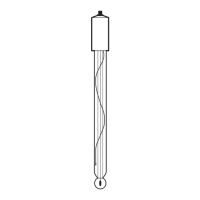
Every load cell has a cord to which is attached a label that displays the
capacity, sensitivity, and resistance of the load cell. Please refer to
Figure 2–10 for information about locating this label. You must enter
the resistance separately for each load cell.
For more information about speed inputs, see page 2-10. Your choices in
this menu are as follows.
Single—Your conveyor is equipped with one speed sensor.
Two—You have two conveyors, each equipped with a speed sensor.
Simulated—There is no speed sensor attached to your conveyor(s).
Load Cell Capacity,
Sensitivity, and
Resistance