Introduction
Hardware Installation
1-10 Micro-Tech 9101/9201 Reference Manual, Rev J Thermo Fisher Scientific
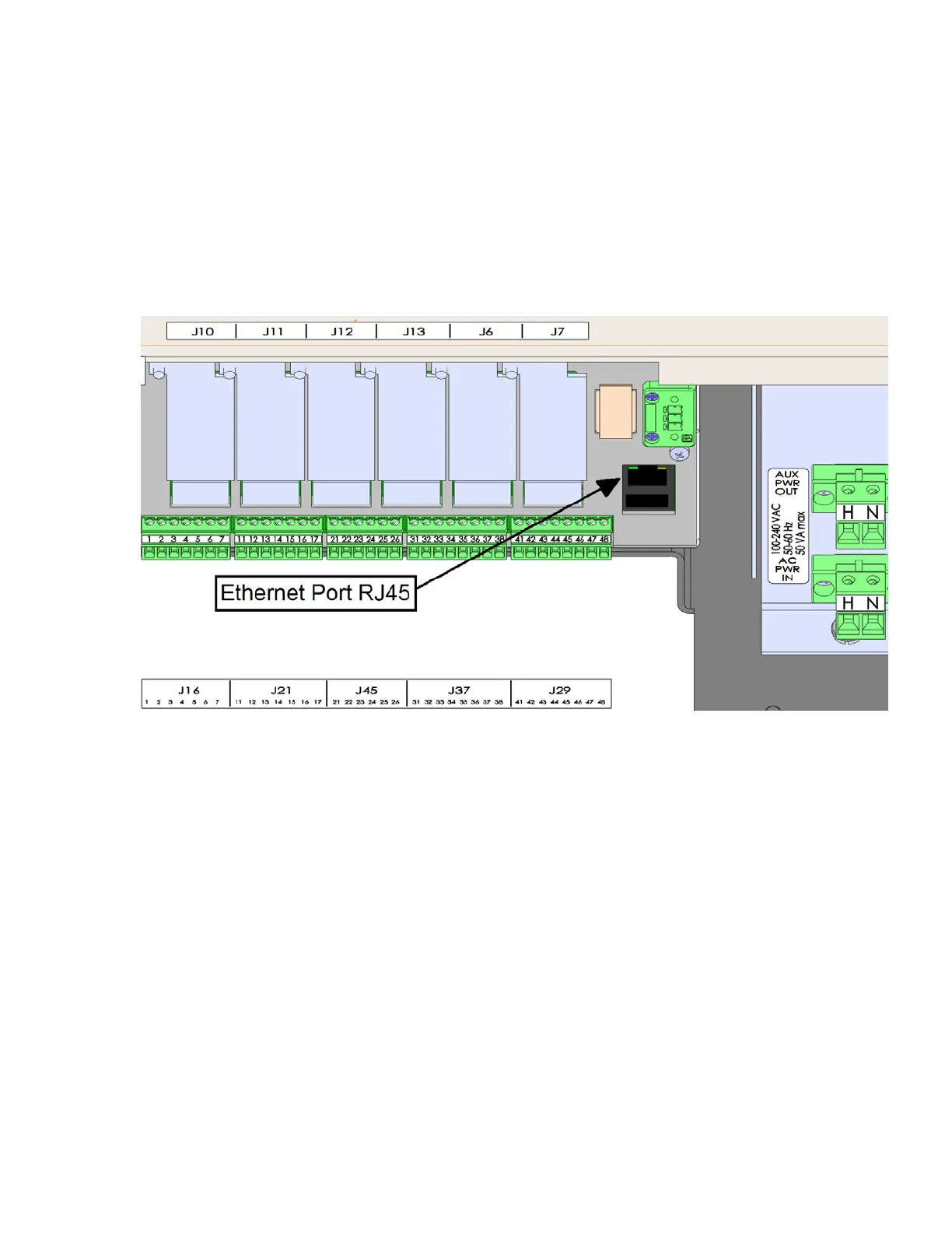
8. In the case of sourcing power for the AC outputs/inputs from the
integrator, source the power from the AUX PWR OUT terminal.
9. All additional field wiring operation at voltages less than 30 V must
be located on the left bottom of the enclosure. Leave ample loose
wiring (typically 8 inches / 20 cm) to facilitate removing the terminal
connectors.
10. Close and latch the enclosure door.
Figure 1–4. Connectors on Underside of Enclosure
This model of the Micro-Tech is designed to be mounted in an
instrument panel. The instrument panel should not be exposed to
excessive vibration, heat, or moisture. The front bezel, when properly
seated, forms a dust seal. A two-inch clearance around the top and
bottom of the Micro-Tech is required for convection cooling. Additional
clearances may be required if other equipment mounted directly below
the Micro-Tech generates excessive heat. A 2-3 inch (50-75mm)
clearance in the back is necessary for wiring access and fuse
replacement. A 1-inch (25mm) clearance on each side is necessary for
inserting the chassis-holding brackets from the back after inserting the
Micro-Tech.
Installing the
Panel Model