Thermo Fisher Scientific Micro-Tech 9101/9201 Reference Manual, Rev J C-67
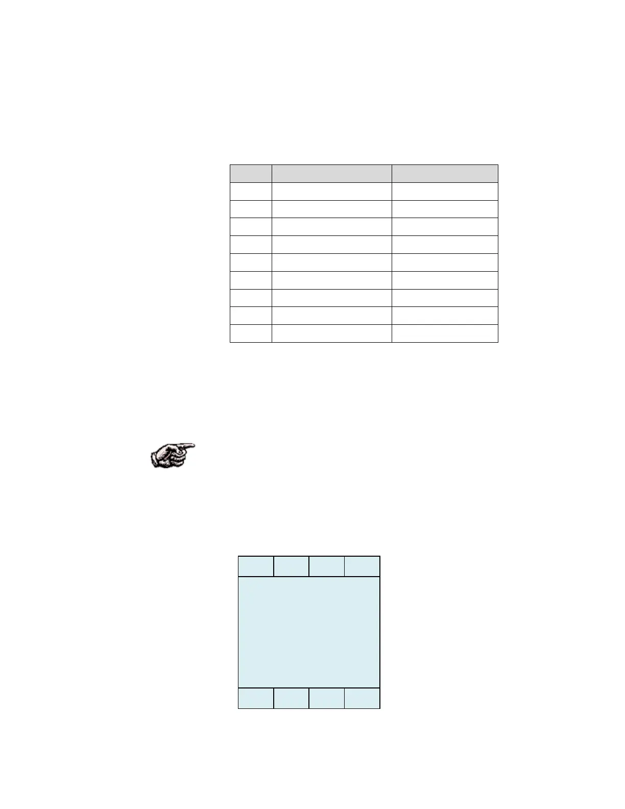
The table below shown the pin-out of the 9 pin Sub-D us connector.
Table C–3. Bus Connector
Connect the green and red cable wires to the screw terminal block located
in the connector, and insure that the shield is making metal to metal contact
with the connector guide. The two pairs of terminals for signal wires A and
B are identical.
NOTE. The same wires (green or red) must always be connected to the
same terminal A or B in all bus terminals and with all bus connections, and
be uniform throughout the segment
After installing the board in one of the free slots (please see the Reference
Manual of the Micro-tech for details) the following screen appears:
Pin Signal Cable
1 Chassis Ground Shield
2 Not Used -
3 RxD/TxD – Data Line B RED wire
4 Not Used -
5 Data Ground -
6 +5VDC (100mA Max) -
7 Not Used -
8 RxD/TxD – Data Line A GREEN wire
9 Not Used -
- SLOT #n CHANGED -
Acquire new
Configuration?