A-44 Micro-Tech 9101/9201 Reference Manual, Rev J Thermo Fisher Scientific
Resistive load: 800 ohms max.
Capacitive load: No limit
Field wiring: Connections are made to the terminal strip on end of
the Analog I/O Board. Note that connector is removable for ease of
termination.
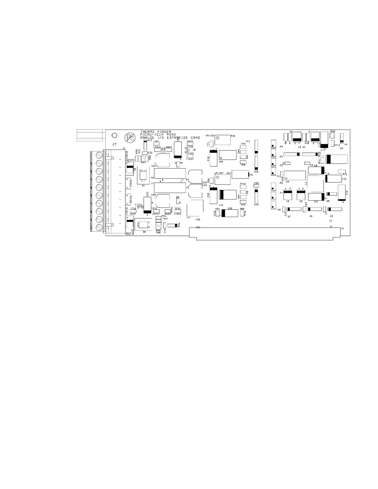
Board Diagram
Part number = 102949
This is an optional board. Install in one of the motherboard expansion
slots J10–J13. For use with model 9101 only.
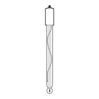
Each load-cell channel provides its own buffer amplifiers for driving the
A/D converter IC’s differential reference voltage from the excitation
sense voltage resistive divider. The load-cell signals are individually
filtered then connected directly to the differential signal input of the A/D
converter. Each load-cell also has an individual R-Cal relay and
individual R-Cal resistor.
“Channel 1,” top connector has jumpers J14 and J15 that allow selection
of either external excitation sense (6-wire LC hook-up) or internal
excitation sense (4-wire LC hook-up).
Load-