User Guide 270
Configuring Layer 2 Multicast Configuration Examples
7
Configuration Examples
7.1 Example for Configuring Basic IGMP Snooping
7.1.1 Network Requirements
Host B, Host C and Host D are in the same VLAN of the switch. All of them want to receive
multicast streams sent to multicast group 225.1.1.1.
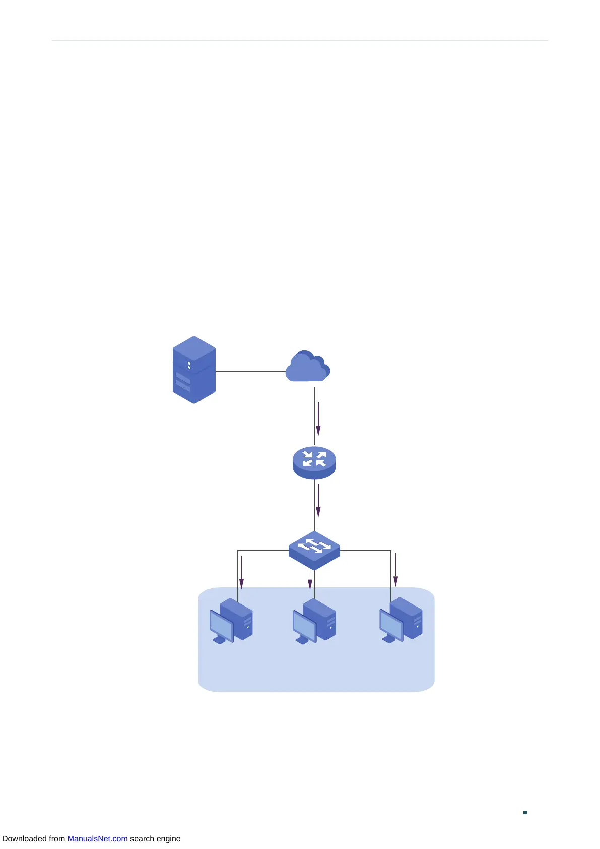
As shown in the following topology, Host B, Host C and Host D are connected to port
1/0/1, port 1/0/2 and port 1/0/3 respectively. Port 1/0/4 is the router port connected to the
multicast querier.
Figure 7-1 Network Topology for Basic IGMP Snooping
Internet
Host B
Receiver
Host C
Receiver
Host D
Receiver
VLAN 10
Querier
Source
Gi1/0/4
Gi1/0/2
Gi1/0/3
Gi1/0/1
7.1.2 Configuration Scheme
■ Add the three member ports and the router port to a VLAN and configure their PVIDs.
■ Enable IGMP Snooping globally and in the VLAN.
Downloaded from ManualsNet.com search engine