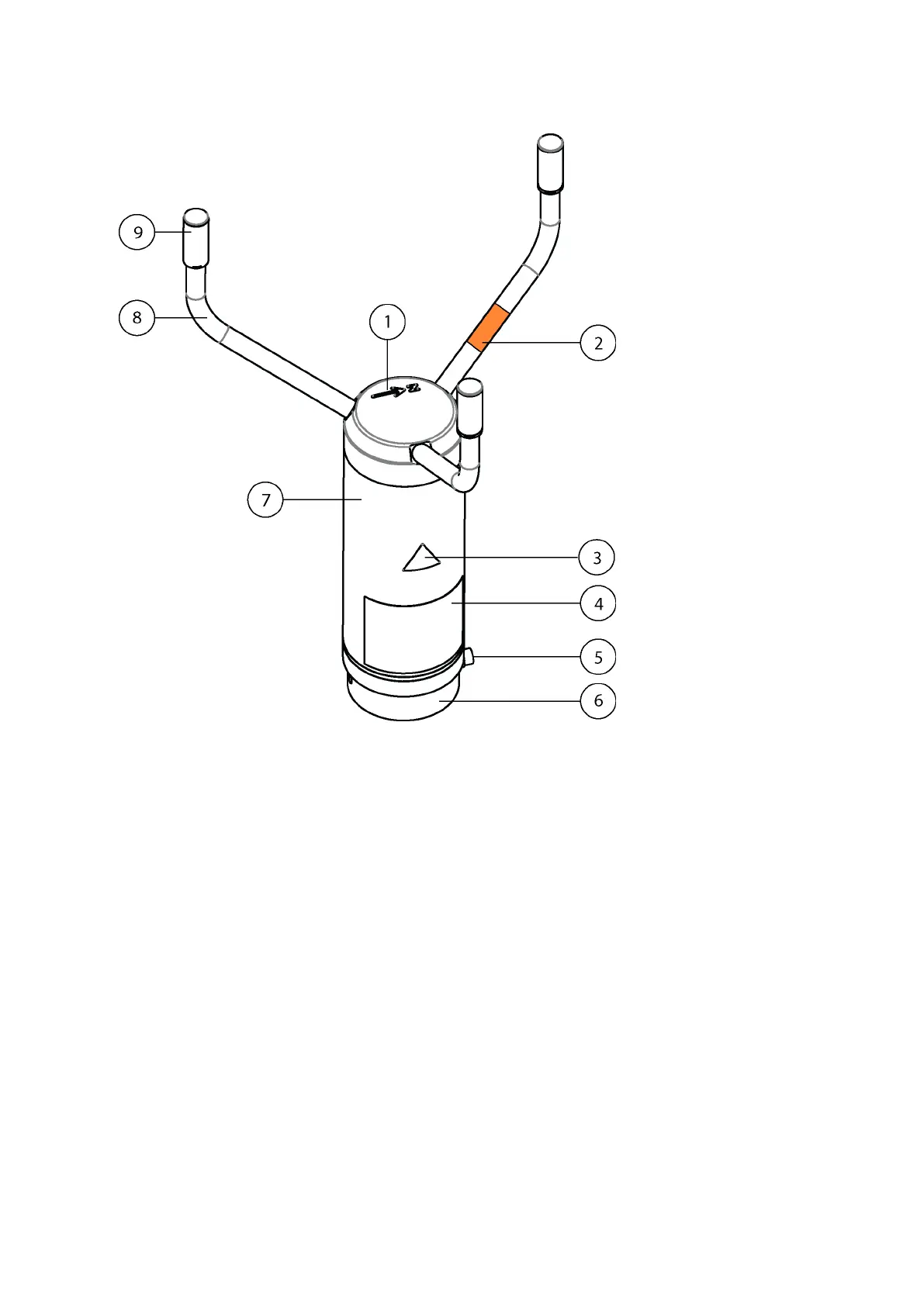
Home
Vaisala
Accessories
WINDCAP WMT700 Series
Vaisala WINDCAP WMT700 Series User Manual
4
of 1
of 1 rating
210 pages
Give review
Manual
Specs
To Next Page
To Next Page
To Previous Page
To Previous Page
Loading...
Figure 1 WMT7
00 Wind Sensor
The arr
ay consis
ts of 1, 8, and 9.
1
T
op of WMT7
00 with North arro
w
2
Or
ange sticker marking North arm
3
Hot warning stick
er
4
T
ype label
5
Mounting scre
w
6
Mounting adapter
7
Body
8
T
ransduc
er arms (3 pcs)
9
T
ransducers (3 pcs
)
WMT700 User Guide
M211095EN-H
12
13
15
Table of Contents
Table of Contents
3
About this Document
11
Version Information
11
Documentation Conventions
11
Trademarks
12
Product Overview
13
Introduction to WMT700
13
WMT700 Wind Sensor
14
Figure 2 WMT700 from below
15
Figure 3 FIX70 Mounting Kit
16
Figure 4 WS425FIX60-POM
17
Figure 5 WMT700FIX60-POM
17
Figure 6 WS425FIX60-RST and WS425FIX60
18
Figure 7 WMT700FIX60-RST
18
Regulatory Compliances
19
Table 2 Environmental Tests
19
Table 3 Electromagnetic Compatibility Tests
19
Ordering Options
20
Table 4 Ordering Options
20
Measurement Range
21
Temperature Range
21
Table 5 Measurement Ranges of Different Sensor Types
21
Table 6 Temperature Range
21
Heating
22
Digital Communication Interface
22
Table 7 Heating
22
Table 8 Digital Communication Interface
22
Digital Communication Profile
23
Digital Communication Units
23
Analog Output Signal for Wind Speed Channel
23
Table 9 Digital Communication Profile
23
Table 10 Digital Communication Units
23
Table 11 Output Configuration
24
Analog Output Signal for Wind Direction Channel
25
Table 12 Analog Output Signal for Wind Direction
25
Connection Cables
26
Mounting Adapters
26
Table 13 Connection Cables
26
Accessories
27
Manual
27
Table 14 Mounting Adapters
27
Table 15 Accessories
27
Table 16 Manual
27
Example of WMT703 Configuration
28
Accessories
28
Figure 8 Example of WMT703 Configuration
28
Bird Cage
29
Zero Wind Verifier
29
Figure 9 Bird Cage
29
Figure 10 Zero Wind Verifier
29
Cables
30
Table 17 Cables
30
Cable Tightening Tool
31
Figure 11 Cable Tightening Tool
31
Functional Description
33
Operating Principle
33
Figure 12 Ultrasonic Measurement Principle
34
Figure 13 Measurement Paths of WMT700
35
Coordinate Systems: Vector and Polar Calculations
36
Wind Speed and Direction Averaging
37
Figure 14 Wind Speed and Direction Presentations (Direction Offset Is 0)
37
Scalar Averaging
38
Wind Direction Coasting
39
Vector Averaging
39
Figure 15 Example of Wind Direction Averaging
39
Measurement Methods
40
Continuous Measurement
40
Wind Measurement on Request
40
Host System Connections and Interfaces
40
Serial Communication and Analog Output
41
Figure 16 WMT700 External Interfaces
41
Serial Communication
42
Communication Interface
42
Profiles
42
Protocols
43
Measurement and Configuration Modes
43
Serial Interface Timing
44
Figure 17 Configuration and Measurement Modes
44
Analog Output
45
Analog Output Types
45
Figure 18 Timing for RS-232, RS-485, and RS-422 Interfaces
45
Figure 19 Frequency Output
46
Analog Output Scaling
47
Table 18 Factory Settings for Analog Wind Speed Output
47
Table 19 Factory Default Settings for Analog Wind Direction Output
47
Table 20 Common Transfer Function Settings for Aout1 (WS)
48
Table 21 Common Transfer Function Settings for Aout2 (WD)
48
Limitations for Output Signals
49
Missing Readings and Error Indication
50
Heating
50
Heated Transducers
51
Heated Transducers and Arms
51
Heated Body, Transducers, and Arms
52
Installation
53
Installing WMT700
53
Maritime Installations
53
Placing WMT700
53
Unpacking and Handling WMT700
54
Figure 20 Removing WMT700 Bottom Transportation Damper
55
Figure 21 Handling WMT700
55
Connecting WMT700 Cable
56
Mounting WMT700 on Vertical Pole Mast
59
Figure 22 Mounting WMT700 on Side of Mast
60
Figure 23 Mounting WMT700 on Top of Mast
60
Mounting WMT700 on Sensor Support Arm or Cross Arm Using WMT70FIX
62
Aligning WMT700
65
Figure 24 WMT700 North Arrow
66
Configuring Wind Direction Offset
67
Analog Output Parameter for WMT700 in Tunnels and Cranes
67
Table 22 Aout_Map Values
67
Table 23 Wind y and X Components at Different Wind Direction Angles
68
Figure 25 WMT700 in Tunnels
69
Figure 26 Ma Output in Tunnels
69
Figure 27 Analog Output for Wind Speed and Wind Speed Alarm
70
Figure 28 Ma Output in Cranes
71
Installing Bird Cage
72
Installing Bird Net
73
Figure 29 WMT700 Bird Cage and Bird Cage Straps
73
Wiring
74
Cables
74
Cable 2 M, Cable 10 M, Cable 15 M, and Cable 26 M
75
Table 24 Connecting Cable 2 M, Cable 10 M, Cable 15 M, and Cable 26 M
75
For COM2 with Cable 2 M and 10 M
76
Figure 30 COM2 RS-485 Wiring
76
Table 25 COM2 RS-485 Wiring
76
Cable 2 M and RS-485 Cable 10 M
77
Connector Signals
77
Figure 31 Pins for 17-Pin M23 Connector
77
Table 26 Connecting RS-485 Cable 2 M (228259SP) and RS-485 Cable 10 M (228260SP)
77
Powering
78
Table 27 Pin-Out for 17-Pin M23 Connector
78
Operating Power
79
Figure 32 Wiring of Non-Heated WMT700 Versions
79
Table 28 Operating Power Supply Voltage Requirements
79
Figure 33 Operating Supply Current Consumption
80
Heating Power
81
Figure 34 Operating Supply Power Consumption
81
Table 29 Heating Power Supply Requirements
81
Figure 35 Wiring of Heated WMT700 Versions, Part 1
82
Table 30 Heating Power and Extension Cable
82
Figure 36 Wiring of Heated WMT700 Versions, Part 2
83
Upgrade from WS425 to WMT700
84
Table 31 Sensor Power of Different Heating Options
84
Table 32 Heabmaxpower Parameter Values
84
Mounting with WS425 Mounting Kit
85
Figure 37 Retrofit Installation to Pole Mast
86
Figure 38 Retrofit Installation to Cross Arm with Array Facing up
87
Upgrade Prerequisites
88
Figure 39 Retrofit Installation to Cross Arm with Array Facing down
88
Figure 40 FIX30, WS425FIX60-RST, and WS425FIX60-POM
89
Figure 41 Mounting Adapter for FIX30, WS425FIX60 (Left), and Mounting Adapter for FIX70 (Right)
89
Upgrading from WS425 to WMT700
90
Table 33 Mounting Kits and Cable Codes
90
Mounting WMT700 with ASOS Mounting Adapter
92
Figure 42 Installing with ASOS Mounting Adapter
92
Connection Cable Prerequisites
94
Wiring in Retrofit Installations
95
Table 34 ROSA Cable 10 M (231425SP)
96
Table 35 Pin-Outs for WS425 Serial Adapter Cable (227569SP)
97
Table 36 Pin-Outs for WS425 Analog Frequency Output Adapter Cable
98
Table 37 Pin-Outs for WS425 Analog Voltage Output Adapter Cable
98
Powering in Retrofit Installations
99
Table 38 WMT700 and WS425 Analog Output Connections
99
Operation
101
Communicating with Terminal Software
101
Entering and Exiting Configuration Mode
102
OPEN - Entering Configuration Mode
102
CLOSE - Exiting Configuration Mode
103
Configuration
103
Parameter Handling Commands
104
Table 39 List of Configuration Mode Commands
104
S - Set Parameter
105
G - Get Parameter
106
BAUD - Display or Set Port Settings
107
Wind Measurement Control Commands
108
MEAS - Single Wind Measurement
108
START - Start Continuous Measurement
108
STOP - Stop Wind Measurement
108
Diagnostics and Support Commands
108
ERRORS - Get Error Codes and Counts
108
CLEARERR - Reset Error Codes and Counts
109
POLL - Get Message
109
RESET - Reset CPU
110
Information Commands
110
Display Command Set
110
H - Display Help and Messages
110
VERSION - Show Firmware Version
110
WIND_GET - Get Calibration Data
111
Configuration Parameters
111
Configurable Data Messages
111
Configuring Data Messages
112
Table 40 Wind Measurement Items for Data Messages
112
Table 41 Control Character
113
Table 42 Monitoring Items for Data Messages
113
Status Flags
115
Table 43 Status
115
Loading Settings from Configuration Files
117
Operating WMT700
119
Operating WMT700 with Terminal Program
120
Data Messages
121
Table 44 Data Messages
121
Missing Readings
126
Error Indication
126
Measurement Mode Commands
127
WMT700 Profile Commands
127
Table 45 Measurement Mode Commands
128
ROSA - MES12 Profile Commands
130
Operating WMT700 in WS425 Analog Output Mode
130
Analog Output Settings
130
Wind Speed Output
131
Frequency
131
Table 46 Required Parameters for WS425 Analog Output Operation Mode
131
Voltage
132
Figure 43 Wind Speed Frequency Analog Output with WS425 Cable and Adapter Cable for Analog Frequency Output
132
Wind Direction Output
133
Figure 44 Wind Speed Voltage Analog Output with WS425 Cable and Adapter Cable for Analog Voltage Output
133
Limitations for Output Signals
134
Missing Readings and Error Indication
134
Figure 45 Wind Direction Voltage Output with WS425 Cable and Adapter Cable
134
Operating WMT700 with WS425 and SDI-12 Profiles
135
Communication Profiles
135
Changing Communication Profile
135
Operating WMT700 with Terminal Program
136
Entering Configuration Mode
137
F/G ASOS Profile
137
Table 47 Configurable Parameters for WS425 F/G ASOS Profile
137
WS425 F/G ASOS Commands
138
Table 48 WS425 F/G ASOS Commands
138
WS425 F/G ASOS Data Message
142
Table 49 WS425 F/G ASOS Data Message
143
WS425 A/B NMEA Standard Profile
144
Table 50 Configurable Parameters for WS425 A/B NMEA Standard Profile
144
WS425 A/B NMEA Standard Data Message
145
WS425 NMEA Extended Profile (V. 0183)
146
Table 51 WS425 NMEA Extended Profile Parameter Descriptions
146
WS425 A/B NMEA Extended Commands
147
WS425 A/B NMEA Extended Data Message
148
Table 52 Checksum Table
148
WS425 A/B ASCII Profile
149
WS425 A/B ASCII Commands
150
Table 53 WS425 A/B ASCII Commands
150
WS425 A/B WAT11 Profile
152
WS425 A/B WAT11 Commands
153
Profile (V 1.3)
153
Table 54 Configurable Parameters for WS425 A/B WAT11 Profile
153
Table 55 Configurable Parameters
154
Commands
155
Table 56 SDI-12 Commands
155
Data Messages
162
WS425 A/B SDI-12 Message for C and M Command
162
WS425 A/B SDI-12 Message for V Command
163
Requesting Cyclic Redundancy Check
163
Maintenance
165
WMT700 Maintenance
165
Testing Operation
166
Troubleshooting
169
Problem Situations
169
Error and Event Messages
171
Table 57 Error and Event Messages
171
Restoring Serial Port Settings
172
Table 58 Restored Serial Port Settings
173
Technical Data
175
Measuring Specifications
175
Table 59 WMT700 Wind Speed Measuring Specifications
175
Table 60 WMT700 Wind Direction Measuring Specifications
175
Electrical Specifications
176
Table 61 WMT700 Electrical Specifications
176
Table 62 WMT700 Output Specifications
176
Environmental Specifications
177
Table 63 WMT700 Environmental Specifications
177
Mechanical Specifications
178
Figure 46 WMT700 Dimensions
178
Table 64 WMT700 Mechanical Specifications
178
Accessory List
179
Figure 47 WMT70FIX Mounting Kit Dimensions
179
Figure 48 ASOS Mounting Adapter Dimensions
179
Table 65 Tools
179
Table 66 Bird Obstructions
180
Table 67 Cables
180
Table 68 WMT700 Mounting Accessories
180
Table 69 WS425 Mounting Accessories
181
Appendix A: Command Set for WMT700
183
Table 70 Command Set for WMT700
183
Appendix B: Typical System Environments
185
Figure 49 System Environment with Serial Port COM1 Only
185
Figure 50 System Environment with Analog Output Only
185
Figure 51 System Environment with Serial Ports COM1 and COM2
186
Figure 52 System Environment with Backup Battery
186
Appendix C: Default Settings for Different Communication
187
Profiles
187
Default Settings for Different Communication Profiles
187
Table 71 Default Settings for Different Digital Communication Profiles
187
Table 72 Parameters with no Protocol-Specific Default Value
188
Appendix D: Configuration Parameter Descriptions
189
Table 73 Configuration Parameter Descriptions
189
Appendix E: WMT700 NMEA MWV Profile
195
Configurable Parameters
195
Table 74 Configurable Parameters for WMT700 NMEA MWV Profile
195
WMT700 NMEA MWV Commands
196
WMT700 NMEA MWV Data Message
197
Missing Readings
197
Appendix F: WMT700 Accessories
199
Figure 53 Complete Set of WMT700 Accessories
199
Appendix G: Certificate
201
Index
203
Warranty
207
Technical Support
207
Recycling
207
Other manuals for Vaisala WINDCAP WMT700 Series
Quick Reference Guide
36 pages
4
Based on 1 rating
Ask a question
Give review
Questions and Answers:
Need help?
Do you have a question about the Vaisala WINDCAP WMT700 Series and is the answer not in the manual?
Ask a question
Vaisala WINDCAP WMT700 Series Specifications
General
Brand
Vaisala
Model
WINDCAP WMT700 Series
Category
Accessories
Language
English
Related product manuals
Vaisala WINDCAP WMT52
143 pages
Vaisala WMS301
32 pages
Vaisala FD12P
154 pages
Vaisala Thunderstorm LS7002
2 pages
Vaisala FS11P
232 pages
Vaisala FS11
176 pages
Vaisala LM21
62 pages