Power Supply Wire Colors Pin
COM1(Service
Port)
RS-485 – Black 9
RS-485 + Brown-Yellow 16
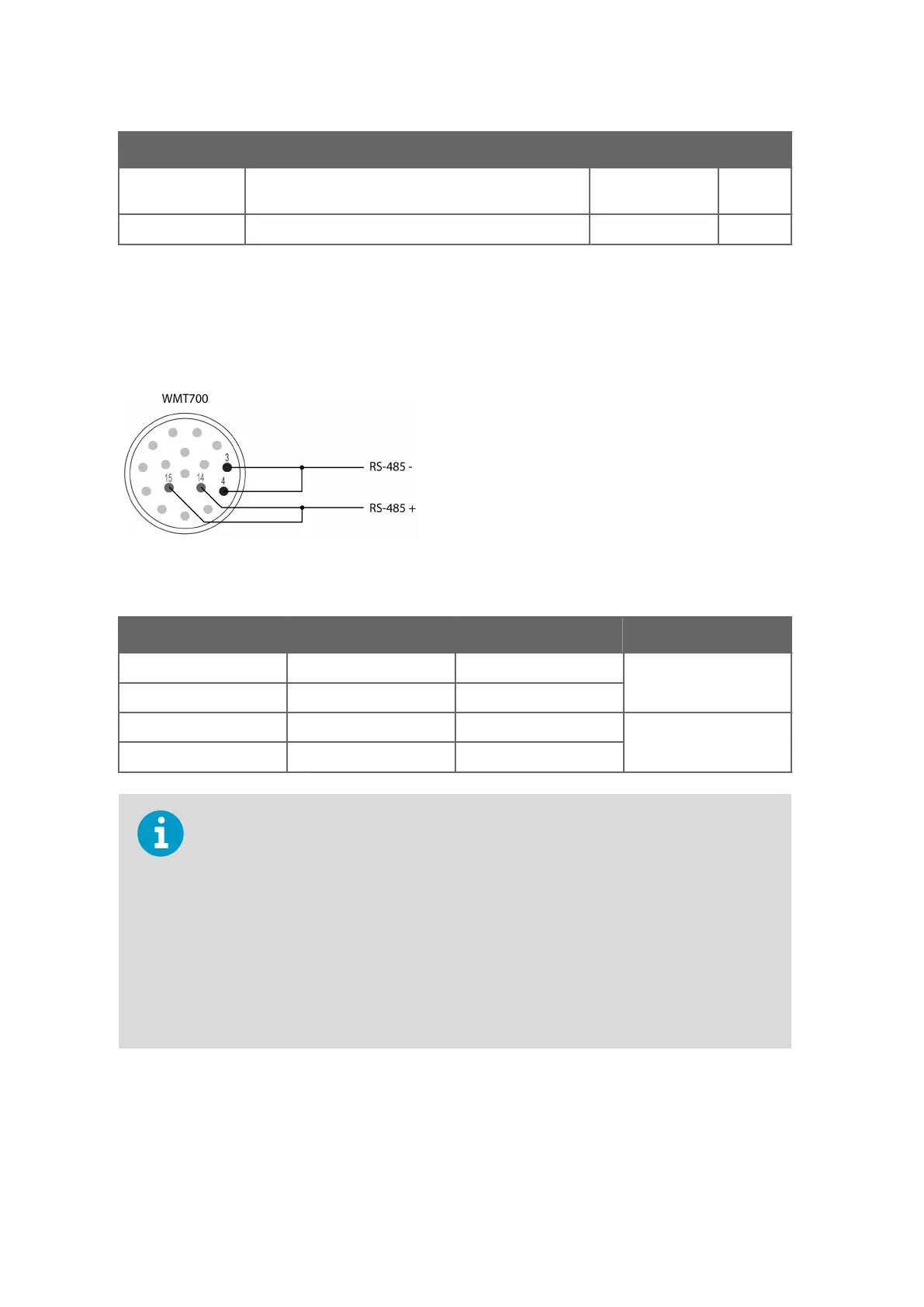
4.9.3 RS-485 for COM2 with Cable 2 m and 10 m
In the RS-485 mode, the same signals as in the RS-422 mode are available at the end of
Cable 2 m and Cable 10 m. Make two-wire loop-backs at the end of the cable.
Figure 30 COM2 RS-485 Wiring
Table 25 COM2 RS-485 Wiring
WMT700 Signals Wire Colors Pin RS485 Signals
RxB Green 3 -
TxB Yellow 4
TxA Brown-Green 14 +
RxA White-Yellow 15
To avoid confusion, the RS-485 and RS-422 signals of WMT700 are named as follows:
• Inverting: –
• Non-inverting: +
According to the EIA-485 standard, the lines are named as follows:
• Inverting: – <=> A
• Non-inverting: + <=> B
The A/B naming used by some manufacturers is in
conflict with the standard. To ensure
proper operation, verify the polarity of the signals when using the device on the bus with
signals named as A/B. Opposite polarity causes data inversion on the bus, but it does not
damage the device.
WMT700 User Guide M211095EN-H
74

 Loading...


