V
W
=0.5·L·(1/t
f
-1/t
r
)
V
W
Wind velocity
L
Distance between two transducers
t
f
Transit time in the forward direction
t
r
Transit time in the reverse direction
Measuring the six transit times allows V
w
to be computed for each of the three ultrasonic
paths. Using V
w
values of two array paths is enough to compute WS and WD.
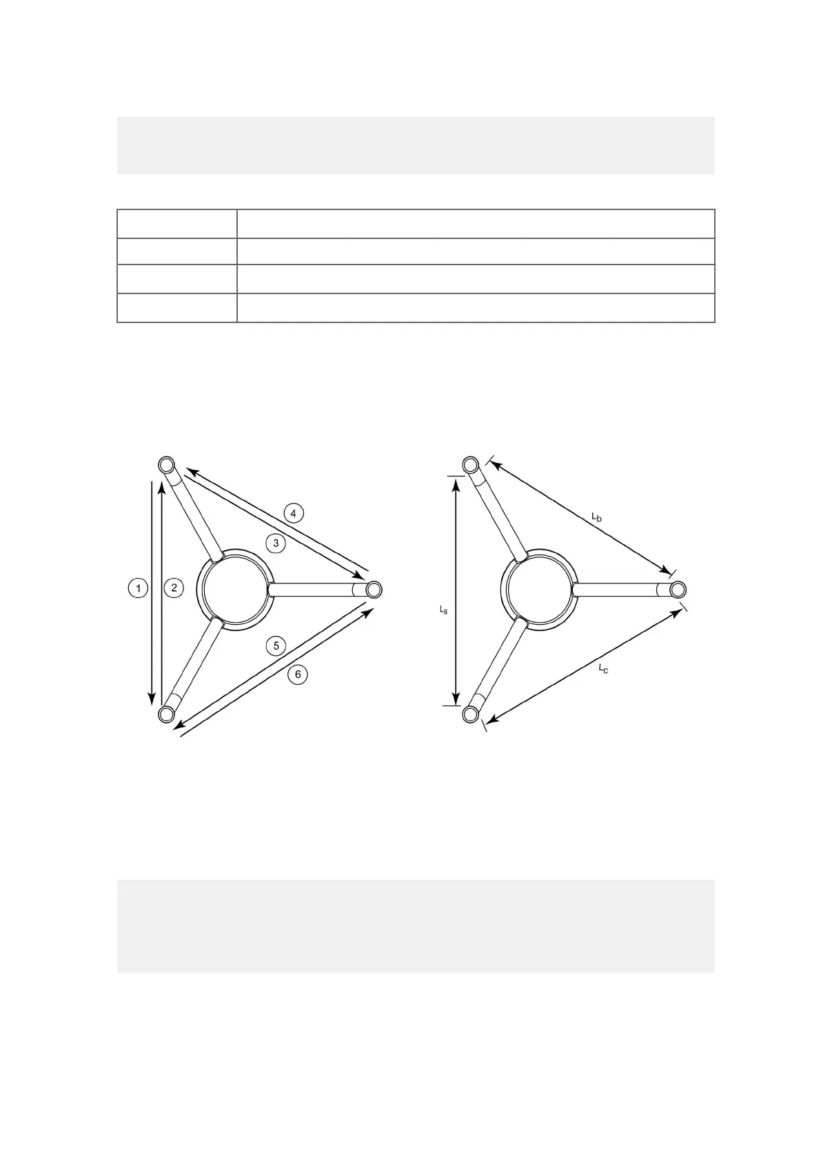
The dierent paths of WMT700 and the vectors provided by the wind sensor:
Figure 13 Measurement Paths of WMT700
1–6 Measurement paths 1 to 6 of WMT700
L
a
, L
b
, L
c
Distance between two transducers
The vectors are calculated as follows:
V
a
=0.5·L
a
·(1/A
1
-1/A
2
)
V
b
=0.5·L
b
·(1/A
3
-1/A
4
)
V
c
=0.5·L
c
·(1/A
5
-1/A
6
)
Chapter 3 – Functional Description
33

 Loading...


