Wire colors in the tables are not applicable to other cables.
If there are unused wires, make sure that they are unconnected and protected. Do not cut
o any wires.
4.9.2 Cable 2 m, Cable 10 m, Cable 15 m, and Cable 26 m
The following table shows how to connect:
• Cable 2 m (227567SP)
• Cable 10 m (227568SP)
• Cable 15 m (237890SP)
• Cable 26 m (237889SP)
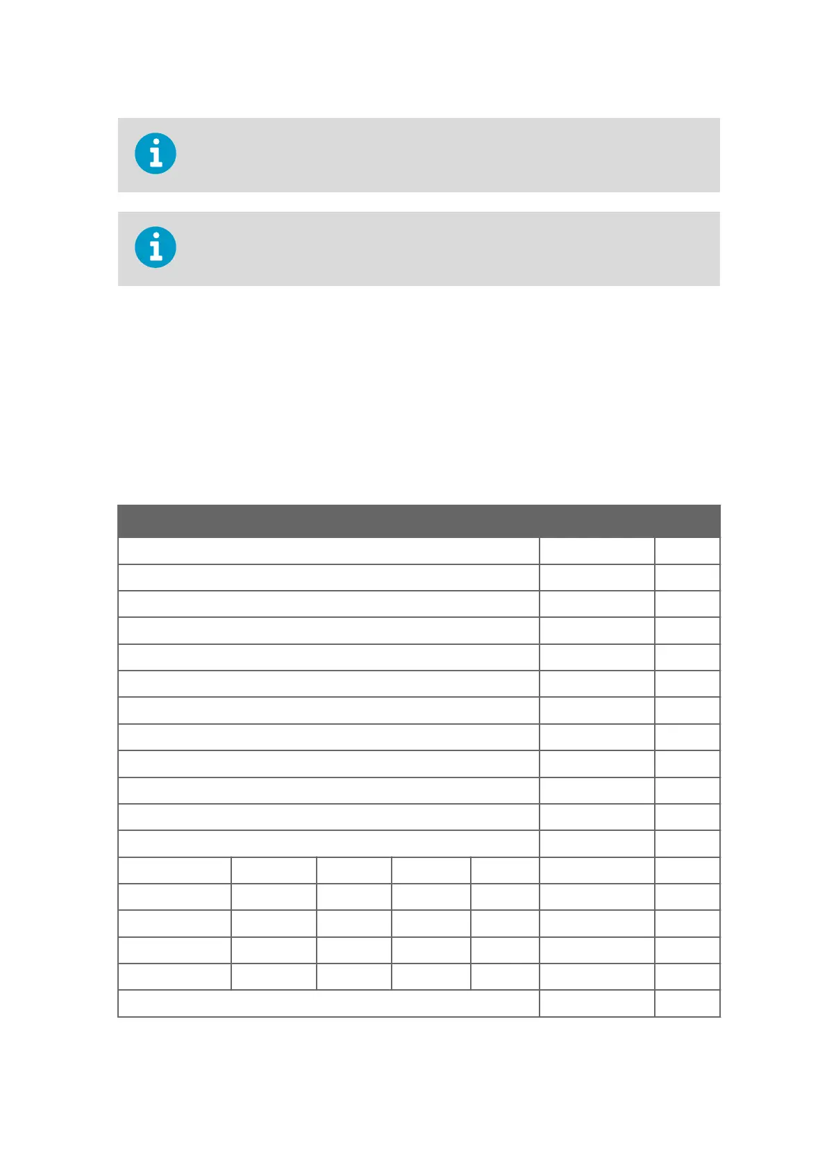
Table 24 Connecting Cable 2 m, Cable 10 m, Cable 15 m, and Cable 26 m
Power Supply Wire Colors Pin
Operating Power Supply White 1
Operating Power Supply Ground Gray-Pink 11
Heater Power Supply Gray 5
Heater Power Supply Pink 6
Heater Power Supply Ground Blue 7
Heater Power Supply Ground Red 8
Enclosure Ground Shield Shield
Analog Outputs
Analog Output AOUT2, Wind Direction Brown 2
Analog Output AOUT1, Wind Speed White-Green 13
Reference Input for AOUT2 (simulated potentiometer) White-Gray 17
Analog Output Ground Red-Blue 12
COM port RS-232 RS-422 RS-485 SDI-12
COM2 RS232Rx Rx– Rx– - Green 3
RS232Tx Tx– Tx– Data Yellow 4
- Tx+ Tx+ - Brown-Green 14
- Rx+ Rx+ - White-Yellow 15
COM1 and COM2 Communication Ports Ground Violet 10
Chapter 4 – Installation
73

 Loading...


