Note that when using separate power supplies for operating and heating, the minus (-)
terminals of the power supplies are connected together by an additional wire. Use a
minimum 0.75 mm
2
wire for connecting the (-) terminals together.
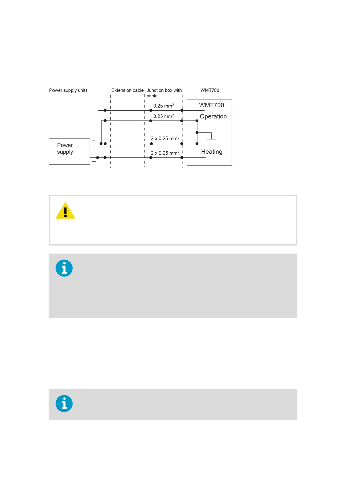
Figure 36 Wiring of Heated WMT700 Versions, Part 2
There are two terminals connected in parallel for both positive and negative
rails of the heating voltage for the maximum current capacity. In case the connection
cable has parallel supply wires, they all have to be connected to ensure current capacity.
Leaving one terminal unconnected or connecting it to the ground may cause a WMT700
malfunction or a short circuit in the power supply.
CAUTION!
Always use cables that meet the minimum dimension requirements. Long cables with thin
wires cause power losses in the cable and significantly decrease the heating capabilities of
WMT700. Loop resistance of 0.15 Ω results in approximately 1 V drop in heating voltage
with 200 W heating. You should note this to get proper heating capability. For example,
the loop resistance of a 10 m cable (227568SP) is 0.7 Ω resulting in an approximately 4 V
drop. It is recommended that you use at least a 28 V supply for the maximum heating
capability.
4.10.2.2 Maximum Peak Power
The heaPeakPwr parameter sets WMT700 maximum peak power (in Watts). WMT700 has
3 heater resistors for each arm. The heaPeakPwr parameter determines how many
resistors are on at the same time. WMT700 measures the supply voltage and calculates the
maximum allowed number of heaters from the supply voltage and heater resistance. The
heaPeakPwr parameter does not limit the power in the body heater of a heated version of
WMT700.
Make sure the WMT700 power peak limit is lower than the power supply rating. Setting
heaPeakPwr value too low reduces heating performance.
Chapter 4 – Installation
81

 Loading...


