4.11.6.3 WMT700 and WS425 Analog Output Signals
WMT700 pin connections dier from the connections of WS425 in that wind speed signal
output, both voltage and frequency signals, appears on WMT700 pin 13.
WMT700 analog outputs must be configured according to the appropriate analog output
mode, which is either voltage, frequency, or potentiometer.
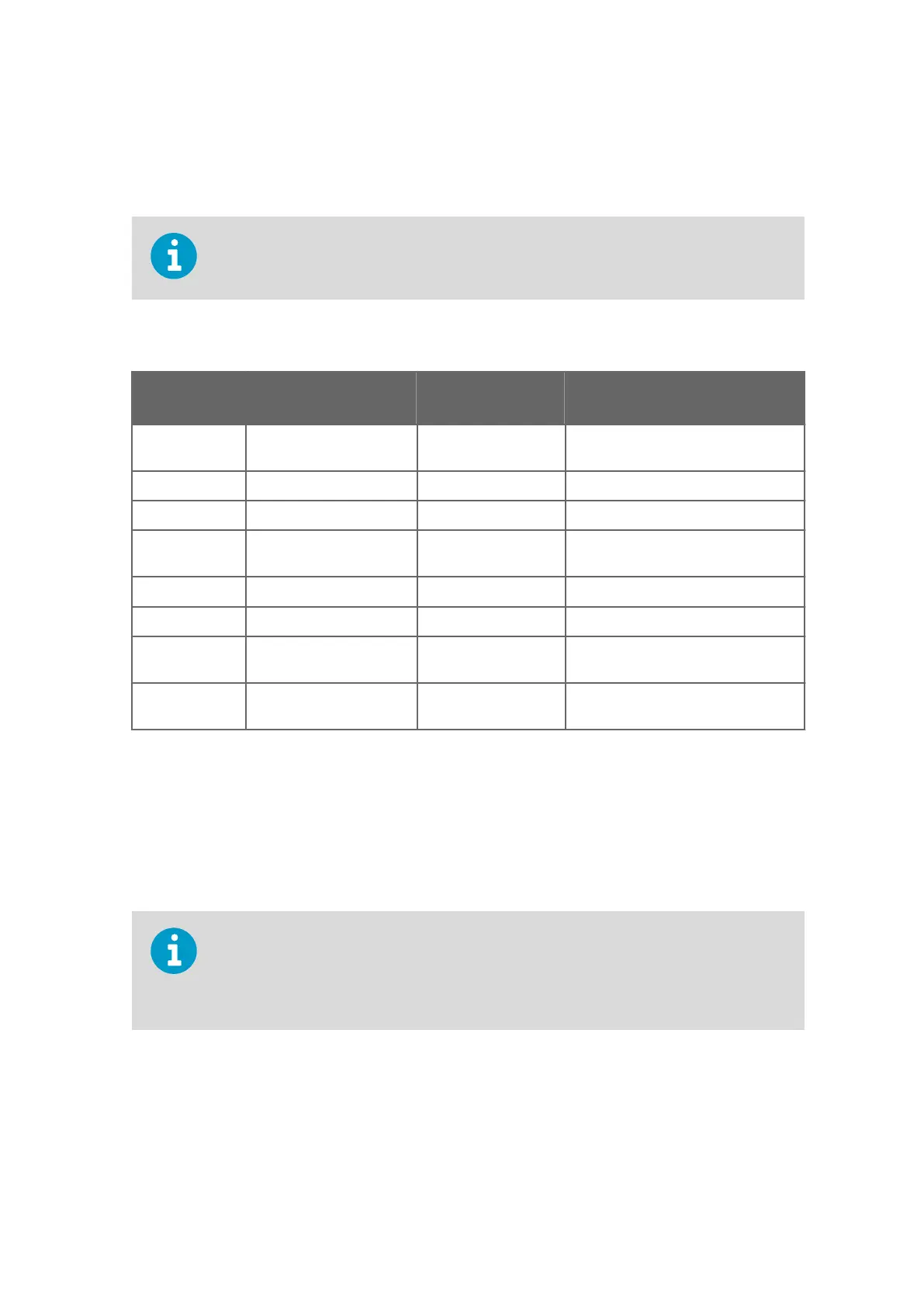
Table 38 WMT700 and WS425 Analog Output Connections
WMT700
Connector Pin
WMT700 Signal
Description
Voltage Output WS425 Connector Pin, Wire Color
13 Analog Output AOUT1,
Wind Speed
Voltage 15, Violet (connect pin 14 to ground)
Current not available
Frequency 14, Pink
2 Analog Output AOUT2,
Wind Direction
Voltage 13, Gray
Current not available
Potentiometer 13, Gray
17 Reference Input for
AOUT2
Potentiometer 12, White
12 Analog Output Ground All modes 1, Black (common with supply
ground)
4.11.7 Powering in Retrofit Installations
WMT700 is designed to operate with the same supply voltages as WS425 and no
connection changes are necessary. The power consumption depends on the selected
heating options. WMT700 with heated transducers can be used to replace similar WS425
models. When upgrading from WS425 to WMT700 with heated transducers and arms, more
capacity is required from the power supply unit.
When WMT700 is in operation, the power consumption is higher than with WS425. This
can
aect system performance in power-critical applications such as solar-powered or
battery-powered systems. Use solar-power or battery backup only to secure operating
voltage. Make sure that the solar-powered system has a sucient power reserve available.
Chapter 4 – Installation
97

 Loading...


