Technical Description
TITANUS
MICRO·SENS
®
36
06/13
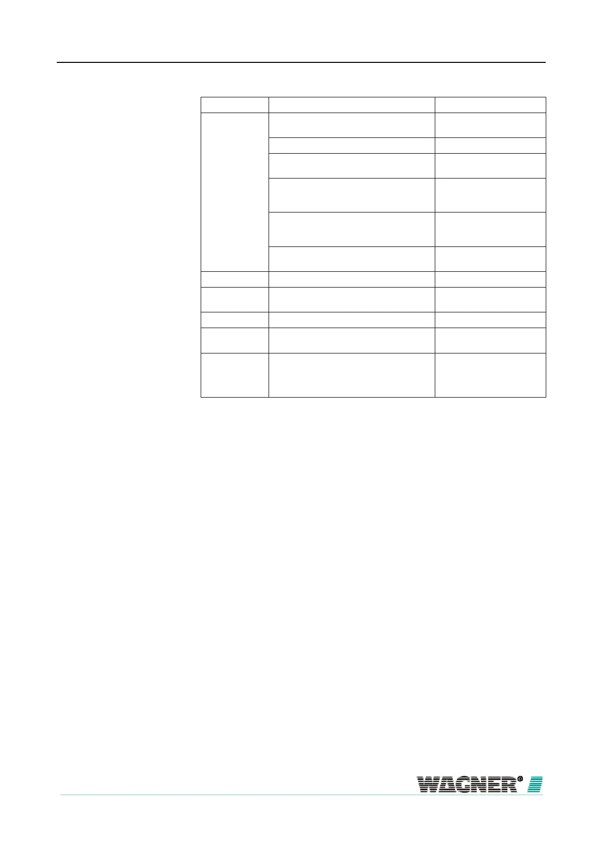
Numbers Function Explanation
1 Smoke level display 1 to 10
(10 yellow LEDs) (*)
Current smoke level
Operation (green LED) Operation display
Fire alarm (red LED) Smoke level (where fire
alarm threshold is set)
Action alarm (red LED) (*) Smoke level (Value as per
fire alarm threshold 10 – 80
% adjustable)
Fault (yellow LED) Pipe system fault or ventila-
tor breakdown or detector
module fault
Infrared interface Commissioning and fault
diagnostics
2 Air sampling pipe connection
for ∅ 25 mm-pipe system
3 Cable feed, fire alarm cable for switching on
FAS and/or power supply (in/out)
2 x M 25
5 Cable feed fire alarm cable 5 x M 20
6 Cable entries (small) 1 x M 20 for cable with
∅ of 8 to 12 mm
7 Cable entries (large) 2 x M 25 for cable with
∅ of 9 to 14 mm
(expandable to ∅ 14 to 18
mm)
(* optional)
Detector bo

 Loading...
