Design
TITANUS
MICRO·SENS
®
80
06/13
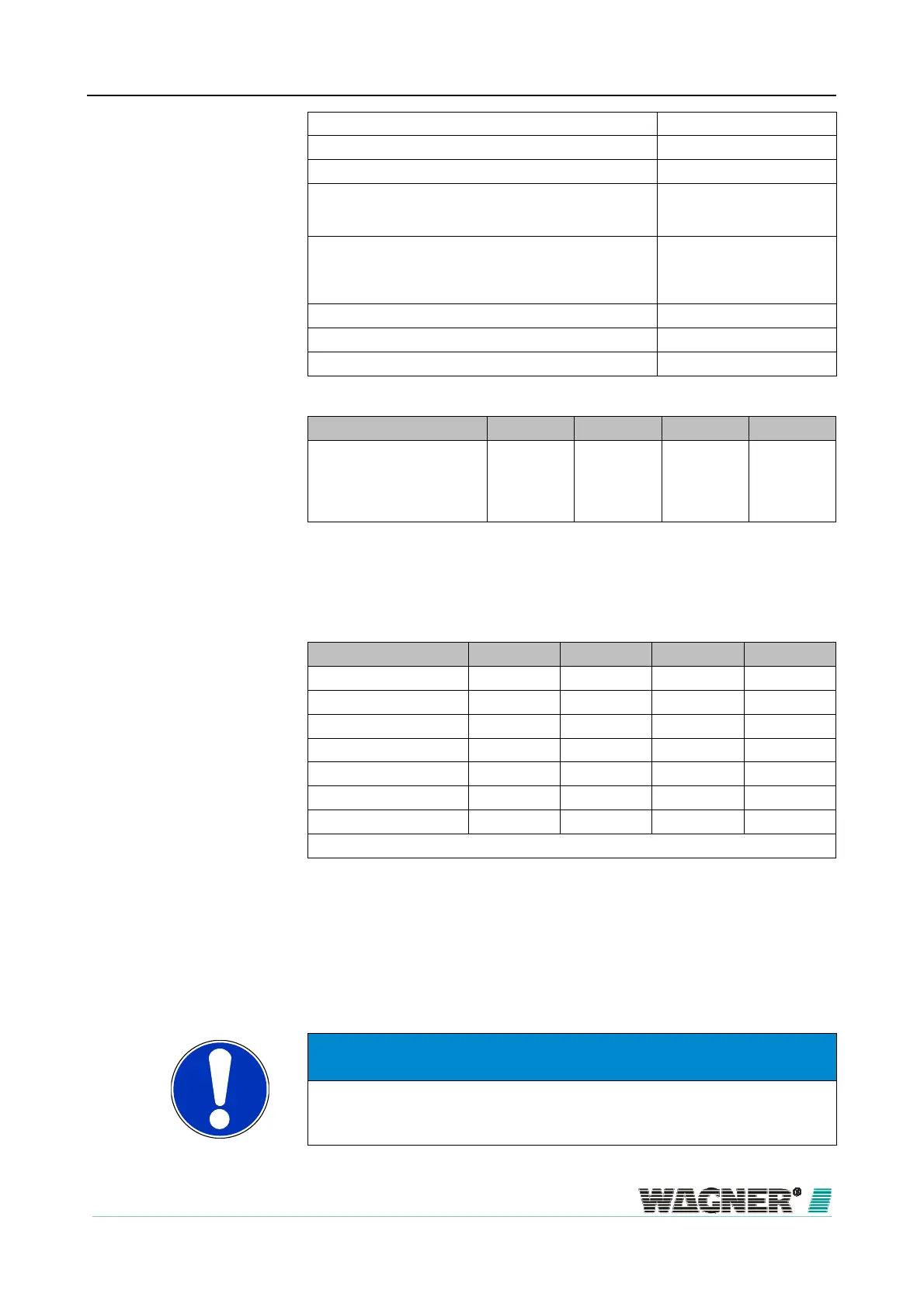
min. distance TITANUS
– T piece 2 m
max. distance TITANUS
– T piece 20 m
max. branch length 25 m
max. overall pipe length per pipe system
Rohr ∅ 25 mm plus
pipe ∅ 12 mm
50 m
8 x 3 m
max. overall pipe length per pipe system per
with high fan voltage 9,0 V
pipe ∅ 25 mm plus
pipe ∅ 12 mm
40 m
8 x 3m
min. distance between 2 aspiration apertures (d) 4 m
max. distance between 2 aspiration apertures (d) 10 m
max. number aspiration apertures (n) per pipe system 8 Stück
Number of apertures 2 4 6 8
Aspiration apertures ∅ in mm*
A
B
C
D
6,0
—
—
—
4,2
4,4
—
—
3,4
3,6
3,6
—
3,0
3,0
3,2
3,2
*) Press cut diameter in aspiration-reducing film sheet
Trigger Thresholds U-Pipe system
Number of apertures 2 4 6 8
1 blocked aperture ±20 % ±10 % — —
2 blocked apertures O ±20 % ±15 % ±10 %
3 blocked apertures O O ±25 % ±20 %
4 blocked apertures O O O ±30 %
5 blocked apertures O O O O
6 blocked apertures O O O O
7 blocked apertures O O O O
… is/are recognised when main air flow set x %
— not possible
O not purposeful
If the blockage of 3 aspiration apertures out of a total of 8 aspiration aper-
tures is recognised, then with the aid of the diagnostics tool, air flow monitor-
ing can be set to ±20 %.
NOTICE
For a project planning according to EN 54-20 or ISO 7240-20, the air flow
monitoring has to be adjusted to ≤20 % in either case.
spiration apertures
Example

 Loading...
