A B
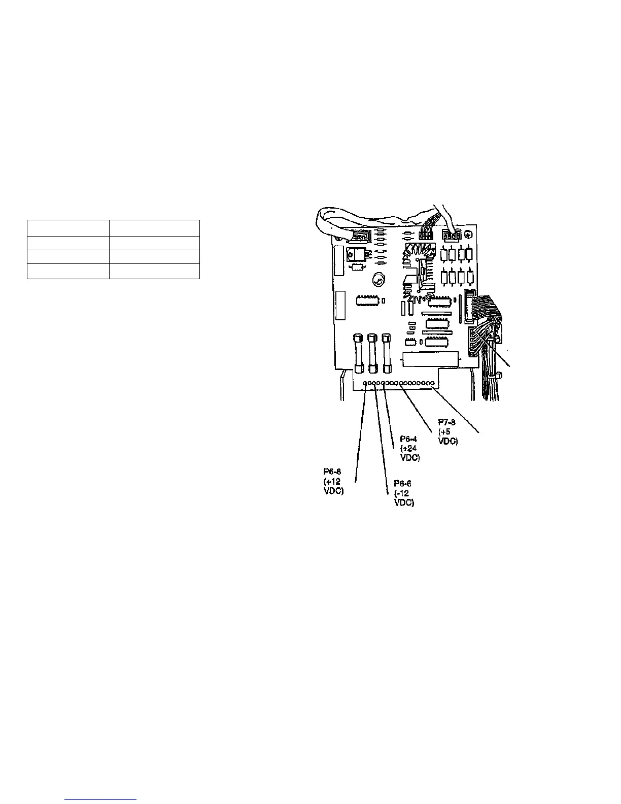
(Figure 3): Connect the negative probe of the DMM to J5-4. Measure
the voltages on the pins in the table.
Connector - Pin
P6-8
P6-6
P6-4
Voltage Range
+11.7 to +12.3 VDC
-11.7 to -12.3 VDC
+23 to +25 VDC
The voltages are correct.
Y N
Ensure that the Power Distribution PWB is correctly plugged into
the Power Supply.
if the problem still exists, replace the Power Supply.
Measure the voltage on P/J7-8.
The voltage is less than +5.10 VDC.
Y N
I Replace the Power Supply (REP 4.1.16).
The voltage Is greater than 4.90 VDC
Y N
Switch off the Scanner and the controlling system. Disconnect
P13 from the Control PWB. Switch on the Scanner.
The voltage on P/J7-8 Is greater than 4.90 VDC.
Y N
Switch off the Scanner. Disconnect the Power Distribution
PWB from the Power Supply (REP 4.1.15). Switch on the
Scanner.
The voltage on P/J7-8 is greater than 4.90 VDC.
Y N
Replace the Power Supply (REP 4.1.16).
Replace the Power Distribution PWB (REP 4.1.15).
D E F
J5-4
Negative
Probe (DC
Common)
Negative
Probe (DC
Common)
Figure 3. Voltage Measurement Points -
Power Distribution PWB
4/97
1.2 DC Power RAP
7356 Scanner
2-8

 Loading...