Replacement
WARNING
High Voltage
Switch off the Scanner and disconnect the Power
Cord.
Note: if the same Exposure Lamp is to be reinstalled, leave the left Lamp
Retaining Clamp in position on the lamp and perform step 1 only for the
remaining clamp.
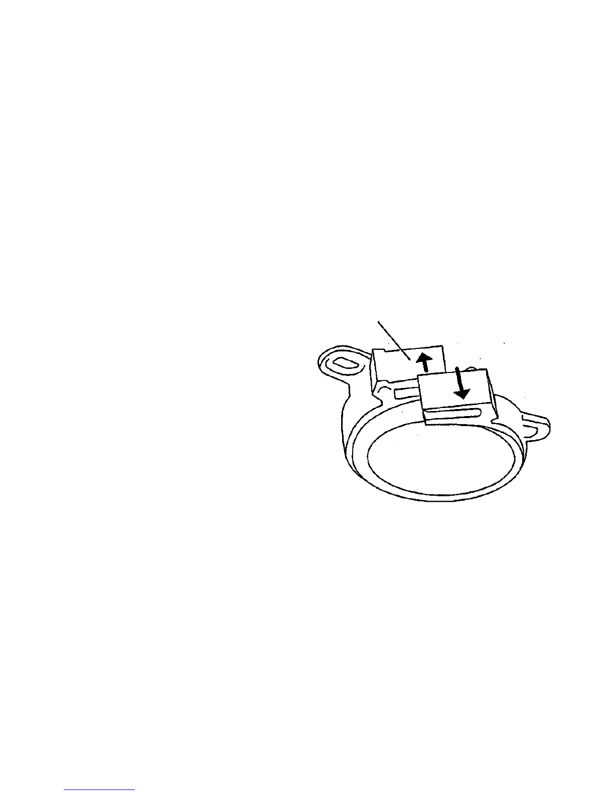
1. (Figure 2): Open each removed Lamp Retaining Clamp by twisting it
until the latch disengages.
2. Install the Exposure Lamp through the hole in the Frame on the left
side.
3. Position the lamp so that it protrudes from the Frame an equal
distance on each side.
Note: If a new lamp is being installed, perform steps 4 and 5 for
each end of the Lamp.
4. Install the clamp over the end of the lamp.
5. Partially close each clamp.
6. For each side of the lamp, position the clamp such that:
• the Exposure Lamp is centered in the large hole in the Frame
• the mounting holes in the clamp are aligned with the holes in the
Frame.
Note: If the lamp cannot be centered in the hole, rotate the Lamp
Retaining Clamp 180 degrees around the Lamp; and perform step 6
again.
7. Install the 2 mounting screws, flat washers, and lock washers.
8. Close each clamp.
9. For each end of the lamp: center the lamp in the large hole in the
Frame, and tighten the two screws.
10. Connect each Lamp Socket.
WARNING
Do not touch the Lamp Sockets while the Scanner Is
energized.
11. Connect the Power Cord and switch on the Scanner.
12. Ensure that the Exposure Lamp illuminates.
NOTE: If the lamp does not illuminate, ensure that the sockets are
correctly connected to the lamp and that the connector wires are not
broken. If the lamp still does not illuminate, go to Section 2 and isolate
the fault.
10. Install the Left Side Panel and the Right Side Panel (REP 4.1.1).
Lamp
Retaining
Clamp
000126A-COB
Figure 2. Opening the Lamp Retaining Clamp
REP 4.1.3
12/97
4-6
7356 SCANNER

 Loading...