February 2013
4-244
ColorQube® 9303 Family
REP 62.1
Repairs/Adjustments
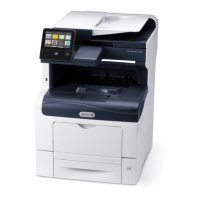
Figure 2 Scanner module removal
8. If a replacement scanner is to be installed, remove the following components:
a. Remove the scanner rear cover, PL 62.10 Item 14.
b. Remove the scanner side cover, PL 62.10 Item 15.
c. Remove the user interface assembly, REP 2.1.
Replacement
1. The replacement procedure is the reverse of the removal procedure.
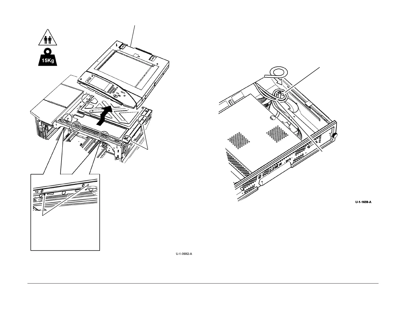
2. Ensure that the SBC PWB and power distribution PWB harnesses are correctly wound
round the post, Figure 3.
Figure 3 Harness winding
2
Slide the scanner mod-
ule off the 2 docking pins
and the 4 base retainers.
3
Remove the scanner module.
1
Remove 2 screws, then push
the scanner to the rear to
unlatch it.
1
Wind the harnesses around
the post as shown.
2
Route the PJs underneath
the harness, then connect
the PJs.

 Loading...