February 2013
4-352
ColorQube® 9303 Family
REP 91.20
Repairs/Adjustments
7. Take note of the routing of the harness. Remove the old marking unit driver PWB to sole-
noid patch PWB harness from the marking unit.
Replacement
1. Replacement is the reverse of the removal procedure.
2. Ensure the new marking unit heater PWB to solenoid patch PWB harness is correctly
routed along the marking unit.
3. Ensure that the ink debris is cleared away from the purge hose connections before
removing or re-attaching the hoses to the reservoir.
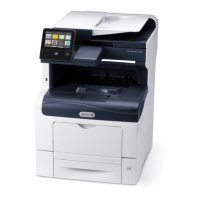
4. Ensure that the purge hoses are located correctly and that the rib on the tube points
towards the drum, Figure 6.
Figure 6 Air tube replacement
5. When replacing the umbilical, ensure that there is only one silicone gasket between the
ink reservoir and umbilical.
CAUTION
Do not use a metal tool to clean the interface area between the umbilical and ink reservoir.
Doing so may cause ink leakage.
6. Ensure there is no ink debris between the ink reservoir and the umbilical before connec-
tion.
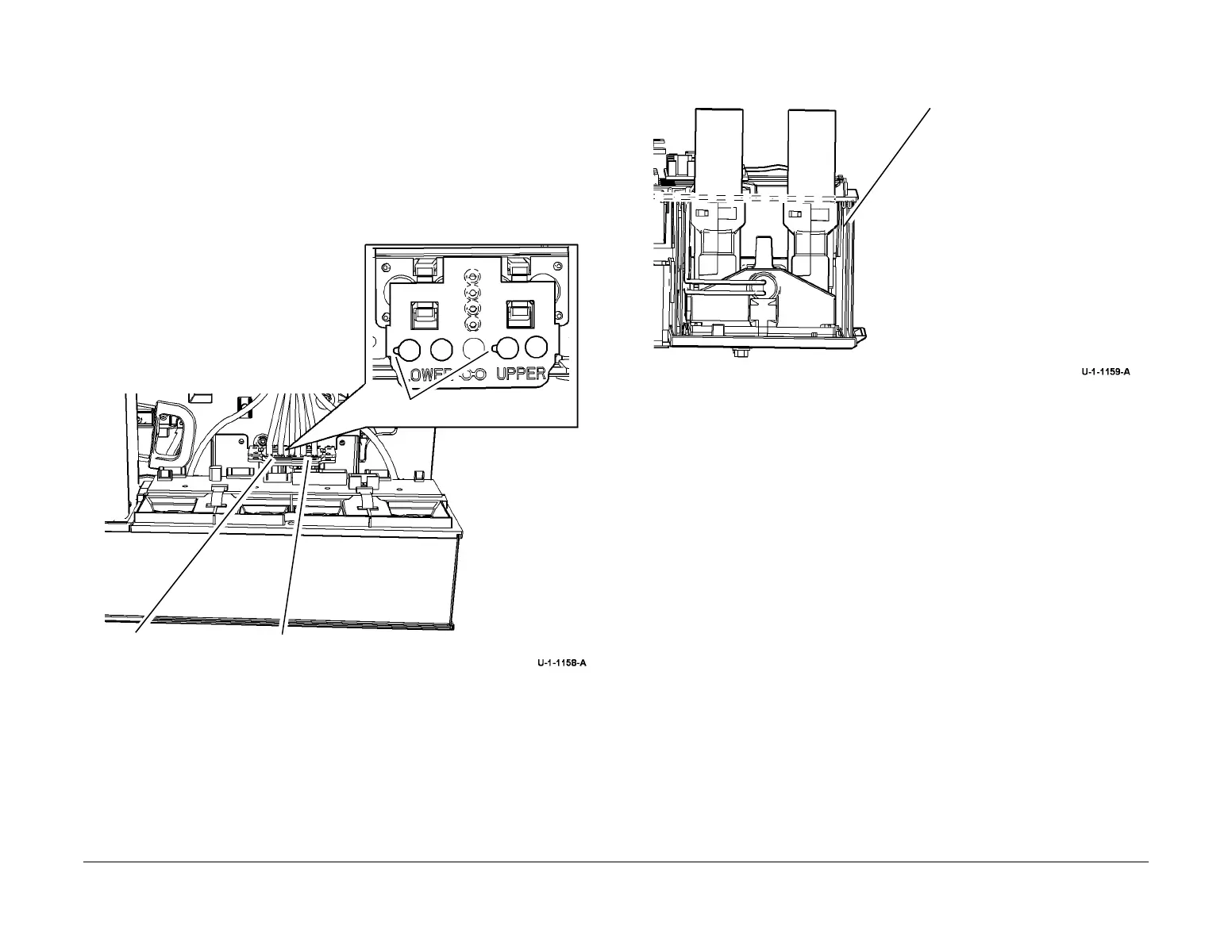
7. Ensure that the umbilicals are seated correctly, Figure 7.
Figure 7 Umbilical seating
8. Firmly tighten the screws on the umbilical clamp, failure to do so can result in ink leaks.
CAUTION
Failure to properly prime the new umbilical will lead to permanent damage to the ink reservoir
and the new umbilical.
NOTE: Only perform Step 9 if a new umbilical has been installed at the same time as the ink
reservoir. If only the ink reservoir has been replaced then go to Step 10 and do not run dC976.
9. Power the machine directly into IME diagnostics mode, refer to GP 1. This will prevent the
thermals from warming up and delivering / pumping ink from the reservoir through the
umbilicals. When the machine has booted into IME diagnostics mode, log into diagnostics
and perform dC976 Ink Delivery Fault Recovery, to prime the umbilicals.
10. Run the relevant diagnostic routines, refer to GP 37 Post Part Replacement Routines.
A
Lower purge hose pair.
B
Upper purge hose pair.
Ribs
1
Ensure the top of the umbilical con-
nector is level with or slightly below
the top of the side insulation,
as shown by the dashed line.

 Loading...