February 2013
6-50
ColorQube® 9303 Family
GP 15
General Procedures/Information
Single Board Controller PWB
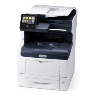
Table 7 indicates the state of the LED’s on a good working single board controller PWB, PL
3.11 Item 13.
Refer to Figure 7 for the location of the LED’s on the single board controller PWB.
Figure 7 Single board controller PWB
3 Tray Module PWB
Table 8 indicates the state of the LED’s on a good working 3 tray module PWB, PL 73.16 Item
4.
Table 7 Single board controller PWB
LED ID LED colour States Description
CR1 Green On 1.8V power is on
CR2 Green Off
On
SIM is good
Indicates a SIM error
CR3 Green On
Off
SIM active
No SIM present
CR4 Green On 3.3V SLEEP present
CR5 Green On 3.3V present
CR7 Green On / Puls-
ing
Various alpha-numeric codes, refer to OF
16. The decimal point is the heatbeat and
pulses.
CR8 Green On +1.8V SLEEP present
CR9 Green On Image clock enabled
CR12 Green On All power good. Appears too as an I/O for
SW assurance that SLEEP power rails are
restored.
CR14 Red Off
On
Normal state
Indicates power failure
CR24 Green Off FPGA is programmed
CR10, CR11,
CR13
- - Not used
Internet connector
left side PJ14
Green / Yellow On
Internet link made.
Green: 1000
Yellow: 100
OFF: 10
Internet connector
right side PJ14
Green / Yellow On
Flashing
Internet activity
Any link
Transmitting or receiving data
Table 8 Three Trays Module PWB
LED ID LED colour Status Description
CR19 Green On +5V present
CR18 Green On +24V present
CR20 Green Flashes LED flashes for 3TM activity

 Loading...