February 2013
6-51
ColorQube® 9303 Family
GP 15
General Procedures/Information
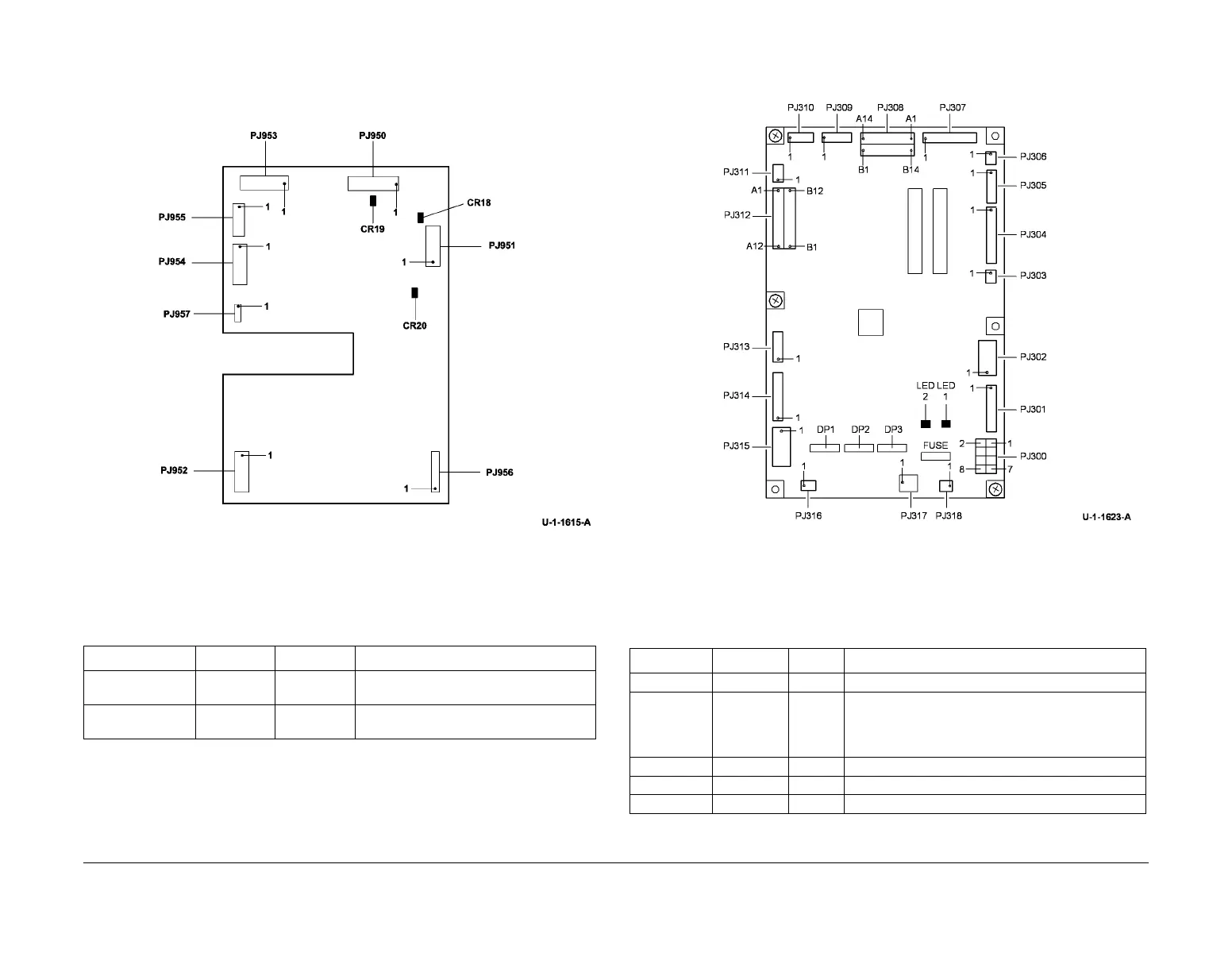
Refer to Figure 8 for the location of the LED’s on the 3 tray module PWB.
Figure 8 3 tray module PWB
LCSS PWB
Table 9 indicates the state of the LED on a good working LCSS PWB, PL 12.75 Item 1.
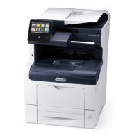
Refer to Figure 9 for the location of the LED’s on the LCSS PWB.
Figure 9 LCSS PWB
HVF PWB
Table 10 indicates the state of the LED’s on a good working HVF PWB, PL 12.140 Item 2.
Table 9 HVF PWB
LED ID LED colour Status Description
LED 1 Red Flashes LED flashes twice a second indicates the
software is running.
LED 2 Red On Indicates that all interlocks are made
(+24V)
Table 10 HVF PWB
LED ID LED colour Status Description
LED 1, 2 Red Not used
LED 3 Red Flashes LED flashes at 2Hz for software operating in normal
mode. This indicates the functioning of the CPU. If
this LED is OFF, the CPU does not function and a new
HVF control PWB is required.
LED 4, 5, 6, 7 Red Not used
LED 8 Red On +24V present and all interlocks are closed
LED 9 Red On +5V present

 Loading...