February 2013
7-6
ColorQube® 9303 Family
PJ Locations
Wiring Data
496 PJ at component OCT offset motor WD 12.23
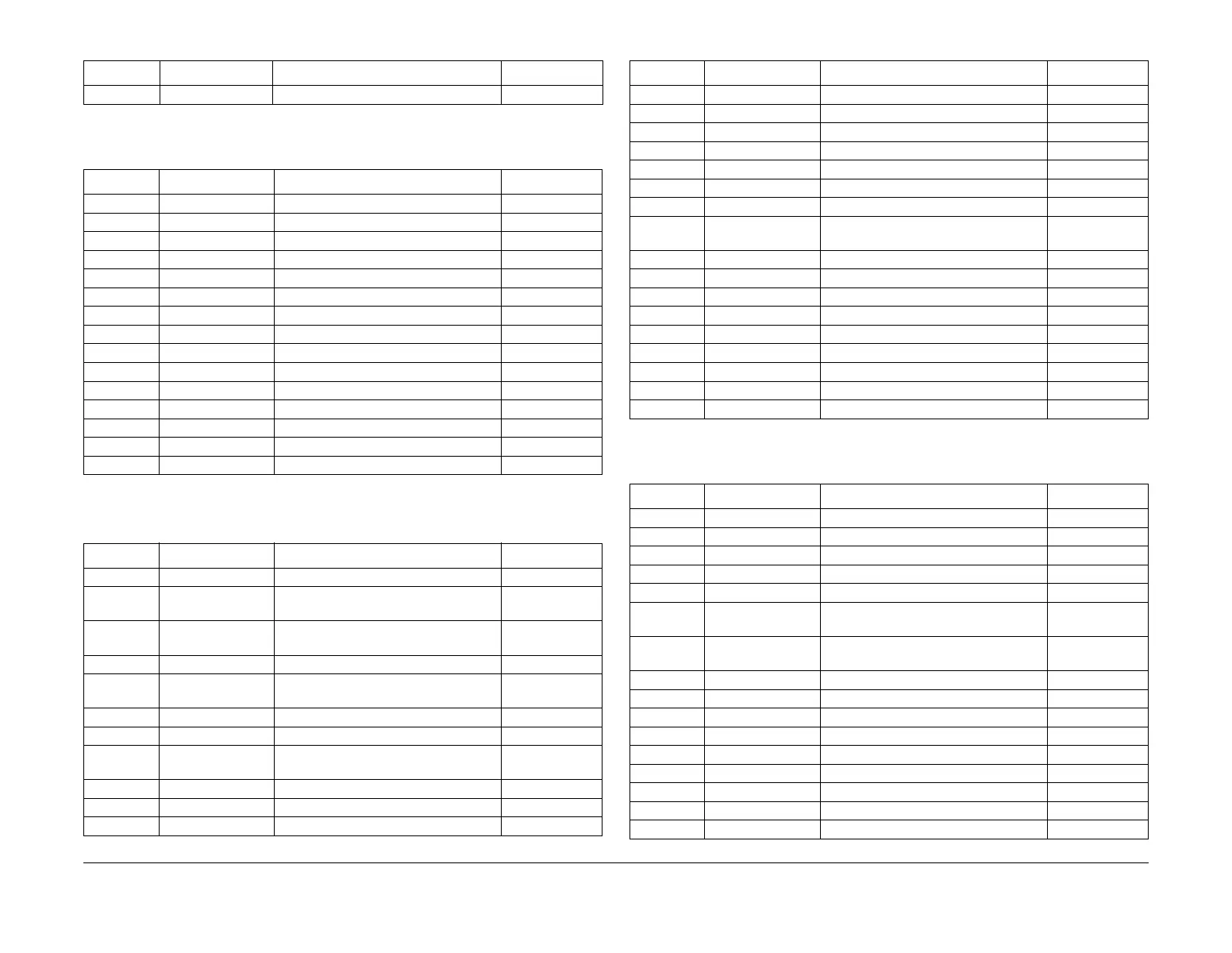
Table 8 PJ500 to PJ549
Connection PJ location figure PJ location Wiring diagram
501 Figure 12 Drum Driver PWB WD 9.1
501 Figure 19 Ink load entry PWB WD 9.17
501 Figure 21 HVF PWB WD 12.12
502 Figure 8 Tray 5 control PWB WD 7.1
502 Figure 19 Ink load entry PWB WD 9.17
502 Figure 21 HVF PWB WD 12.13
503 Figure 8 Tray 5 control PWB WD 7.1
503 Figure 21 HVF PWB WD 12.24
504 Figure 8 Tray 5 control PWB WD 7.1
505 Figure 8 Tray 5 control PWB WD 7.2
506 Figure 8 Tray 5 control PWB WD 7.2
507 Figure 8 Tray 5 control PWB WD 7.2
511 Figure 8 Tray 5 control PWB WD 7.2
513 Figure 8 Tray 5 control PWB WD 7.1
530 Figure 22 In-line connector WD 7.1
Table 9 PJ550 to PJ599
Connection PJ location figure PJ location Wiring diagram
551 Figure 25 BM PWB WD 12.16
552 Figure 25 BM PWB WD 12.16, WD
12.17
553 Figure 25 BM PWB WD 12.16, WD
12.17
554 Figure 25 BM PWB WD 12.17
555 Figure 25 BM PWB WD 12.17, WD
12.18
556 Figure 25 BM PWB WD 12.18
557 Figure 25 BM PWB WD 12.18
559 Figure 25 BM PWB WD 12.6, WD
12.19
560 Figure 25 BM PWB WD 12.19
562 Figure 25 BM PWB WD 12.19
563 Figure 25 BM PWB WD 12.19
Table 7 PJ450 to PJ499
PJ number PJ location figure PJ location Wiring diagram
566 PJ at component BM Backstop Guide Home Sensor WD 12.18
567 PJ at component BM Tamper Home Sensor WD 12.18
568 PJ at component BM Paper Present Sensor WD 12.18
570 PJ at component BM Exit Sensor WD 12.18
571 PJ at component BM Stapler Head Carrier Closed Sensor WD 12.16
572 PJ at component BM Crease Blade Home Sensor WD 12.16
573 PJ at component BM Crease Roll Gate Home Sensor WD 12.16
574 PJ at component BM Crease Blade Motor Encoder Sen-
sor
WD 12.16
575 PJ at component BM Crease Roll Motor Encoder Sensor WD 12.17
576 PJ at component Bin 2 WD 12.17
577 PJ at component Bulkhead Connector WD 12.18
581 PJ at component Backstop Assembly WD 12.17
582 PJ at component Backstop Assembly WD 12.17
583 PJ at component Tri-folder attachment WD 12.18
585 PJ at component BM Stapler Head 1 WD 12.16
586 PJ at component BM Stapler Head 2 WD 12.16
590 Figure 17 Quad wave amplifier PWB WD 9.13
Table 10 PJ600 to PJ899
Connection PJ location figure PJ location Wiring diagram
601 Figure 12 Drum Driver PWB WD 9.2
601 no link Cleaning Unit PWB WD 9.19
601 Figure 21 HVF PWB WD 12.13
601 Figure 10 Media path driver PWB Not used
601 Figure 19 Ink load entry PWB WD 9.18
601 Figure 23 Tri folder PWB WD 12.6, WD
12.20
601 Figure 20 Printhead PWB WD 9.20, WD
9.21
602 Figure 12 Drum Driver PWB WD 9.2
602 no link Cleaning Unit PWB WD 9.19
602 Figure 21 HVF PWB WD 12.13
602 Figure 23 Tri folder PWB WD 12.20
603 Figure 12 Drum Driver PWB WD 9.2
603 Figure 23 Tri folder PWB WD 12.20
604 Figure 23 Tri folder PWB WD 12.20
604 no link Inline connector between PS and HDD WD 1.5
605 Figure 16 Marking unit driver PWB WD 9.11
Table 9 PJ550 to PJ599
Connection PJ location figure PJ location Wiring diagram

 Loading...