108 Zebra ZXP Series 3 Card Printer Service Manual P1061317-002
5: Replacement Procedures
Procedures
Replacement
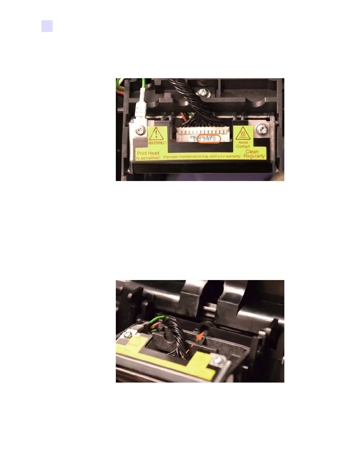
Step 1. Record the resistance (e.g., 3161 Ω circled below) of the new Printhead.
Step 2. Connect the 4-wire Color Ribbon Sensor.
Step 3. Connect the printhead data and power cable. Note that the connector is keyed. Use a
small flat-blade screwdriver to guide the connector into place.
Step 4. Connect the green ground wire.
Step 5. Insert the 4-wire connector back through the hole in the frame. Failure to do so
may cause the printhead frame to be broken when the Lid is closed.
Step 6. Push the printhead alignment pin into the alignment hole (arrow below).
Step 7. Press in and downward, lowering the Printhead into place.
Step 8. The Printhead installation is complete.
 Loading...


