11.3.1 16-bit timer/counter mode
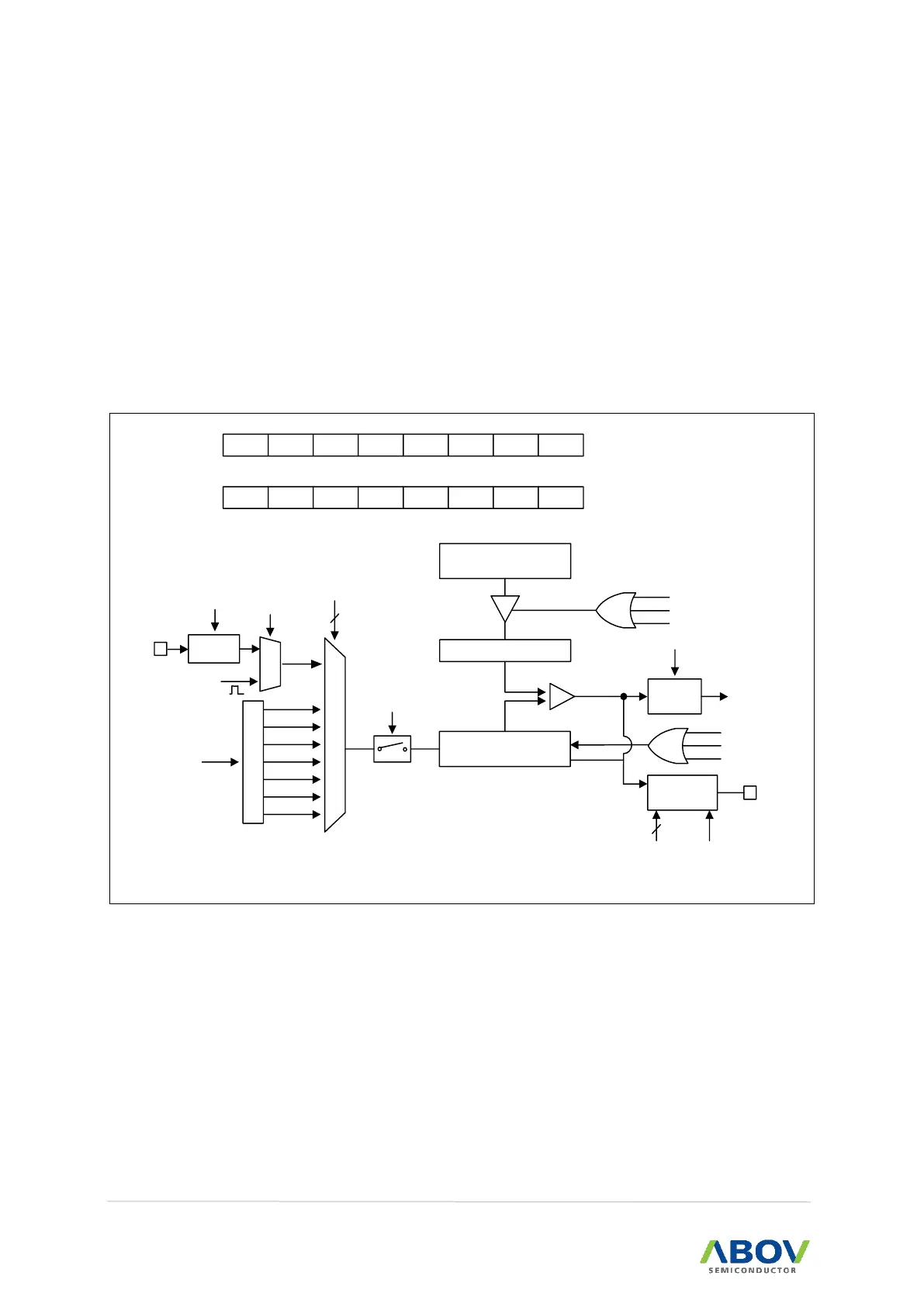
16-bit timer/counter mode is selected by control registers, and the 16-bit timer/counter has counter
registers and data registers as shown in Figure 49. The counter register is increased by internal or
timer 1 A match clock input.
Timer 2 can use the input clock with one of 1, 2, 4, 8, 128, 512, external clock (EC2) and T1 A Match
prescaler division rates (T2CK[2:0]). When the values of T2CNTH/T2CNTL and T2ADRH/T2ADRL are
identical to each other in timer 2, a match signal is generated and the interrupt of Timer 2 occurs. The
T2CNTH/T2CNTL values are automatically cleared by the match signal. It can be cleared by software
(T2CC) too.
T2MS[1:0]
T2POL
A Match
T2CC
T2EN
P
r
e
s
c
a
l
e
r
fx
M
U
X
fx/2
fx/4
fx/64
fx/512
fx/2048
fx/8
fx/1
16-bit Counter
T2CNTH/T2CNTL
Clear
Comparator
16-bit A Data Register
T2ADRH/T2ADRL
T2IFR
INT_ACK
Clear
To interrupt
block
A Match
Buffer Register A
Reload
Pulse
Generator
T2O
R
T2EN
3
T2CK[2:0]
2
A Match
T2CC
T2EN
T2EN
T2CRH
1
ADDRESS:C3H
INITIAL VALUE : 0000_0000B
–
T2MS1 T2MS0
– – –
T2CC
–
0 0
– – –
X
T2CK2
T2CRL
X
ADDRESS:C2H
INITIAL VALUE : 0000_0000B
T2CK1 T2CK0 T2IFR T2ECS T2POL T2ECE T2CNTR
X X X X X X X
M
U
X
Edge
Detector
T2ECE
T2ECS
T1 A Match
EC2
 Loading...