10 Watch timer
Watch timer (WT) has functions for RTC (Real Time Clock) operation which are generally used for
RTC design. The WT consists of a clock source select circuit, a timer counter circuit, an output select
circuit and watch timer control registers.
Before starting the WT operation, a user needs to determine an input clock source and output interval,
and to set WTEN of the WTCT to ‘1’. It is able to execute simultaneously or individually. To stop or
reset the WT, the WTEN bit must be cleared. When the CPU is in STOP mode, a sub clock can be
alive so that the WT continues its operation.
Watch timer counter circuits may be composed of 21-bit counter which contains low 14-bit with binary
counter and high 7-bit counter in order to increase resolution. By configuring the WTDR, it is possible
to control WT clear, set interval value at write time, and read 7-bit WT counter value at read time.
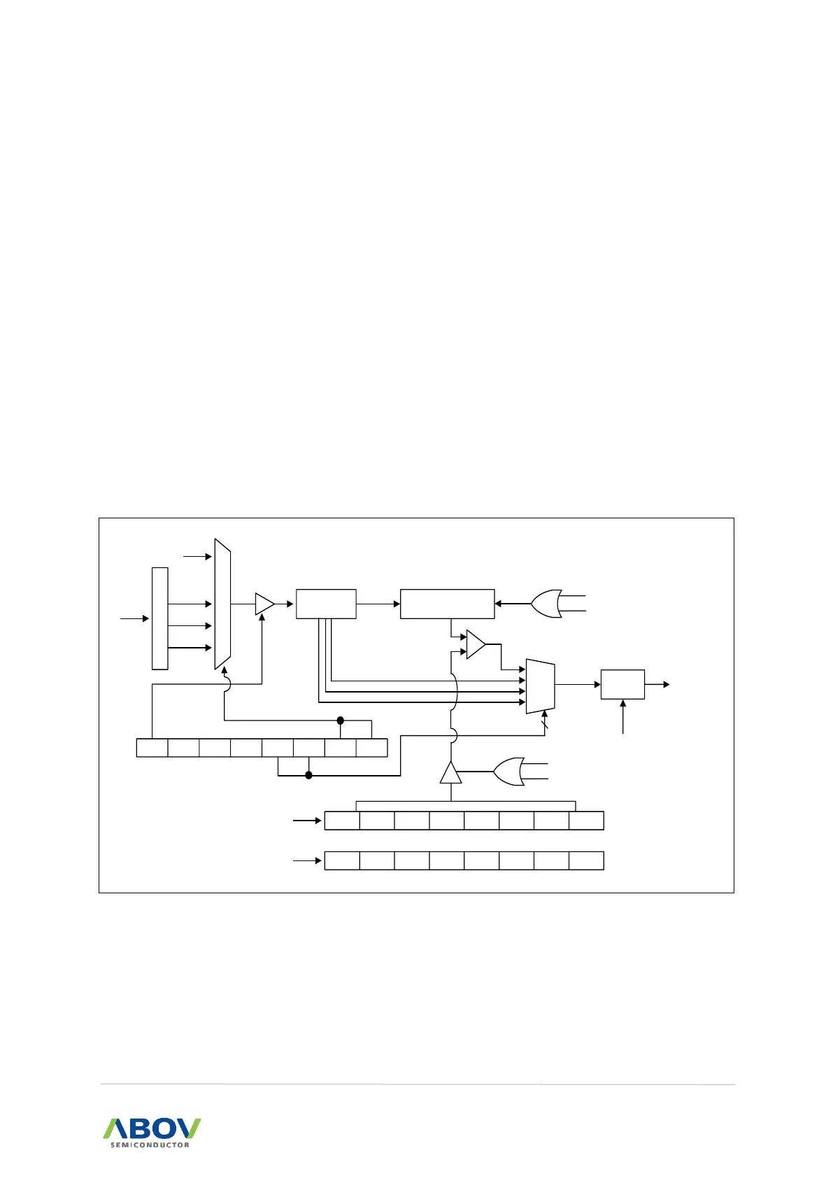
10.1 WT block diagram
In this section, the WT of A96G166/A96A166/A96S166 is described in a block diagram.
P
r
e
s
c
a
l
e
r
fx
M
U
X
fSUB
fWCK
14Bit
Binary Counter
Timer counter
fWCK /2
14
WTCR WTEN
- -
WTIFR WTIN1 WTIN0 WTCK1 WTCK0
MUX
fWCK /2
14
fWCK /2
13
fWCK /2
7
WTIFR
To interrupt
block
WTCL WTDR6 WTDR5 WTDR4 WTDR3 WTDR2 WTDR1 WTDR0
WTDR
Write case
- WTCNT6 WTCNT5 WTCNT4 WTCNT3 WTCNT2 WTCNT1 WTCNT0
WTCNT
Read case
Clear
INT_ACK
fx/64
fx/128
fx/256
2
fWCK
14
/(2 X(7 bit WTDR Value +1))
Comparator
match
Reload
Match
WTCL
Clear
Match
WTCL