If more than 2 samples have logical low level, it is considered that a valid start bit is detected and the
internally generated clock is synchronized to the incoming data frame. And the data recovery can
begin. The synchronization process is repeated for each start bit.
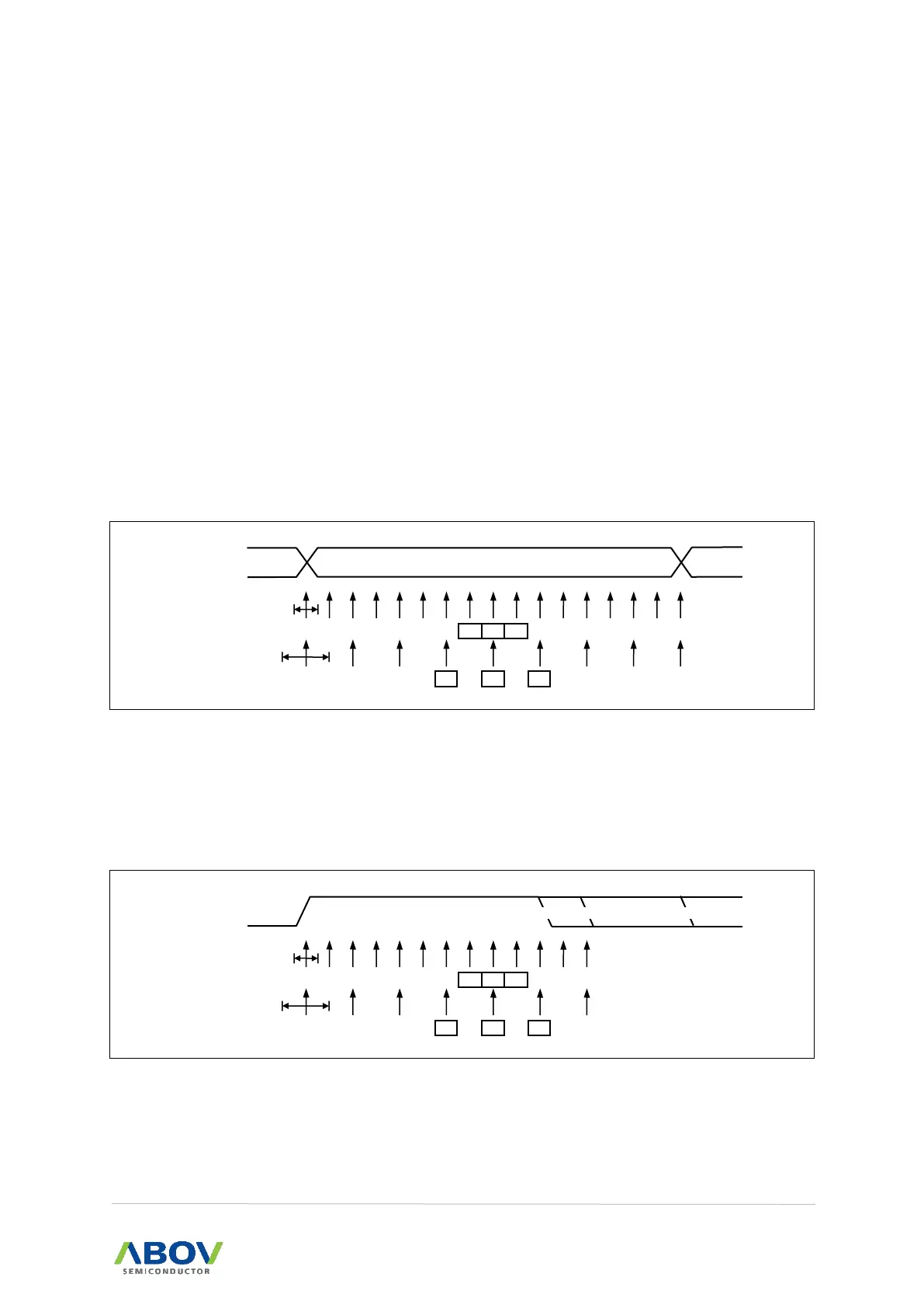
As described above, when the Receiver clock is synchronized to the start bit, the data recovery can
begin. Data recovery process is almost similar to the clock recovery process. The data recovery logic
samples 16 times for each incoming bits for Normal mode and 8 times for Double Speed mode. And
uses sample 8, 9, and 10 to decide data value for Normal mode, samples 4, 5, and 6 for Double
Speed mode.
If more than 2 samples have low levels, the received bit is considered to a logic 0 and more than 2
samples have high levels, the received bit is considered to a logic 1. Data recovery process is then
repeated until a complete frame is received including the first stop bit. The decided bit value is stored
in the receive shift register in order. Note that the Receiver only uses the first stop bit of a frame.
Internally, after receiving the first stop bit, the Receiver is in idle state and waiting to find start bit.
Figure 75. Sampling of Data and Parity Bit
A process for detecting stop bit is similar to the clock and data recovery process. That is, if 2 or more
samples of 3 center values have high level, correct stop bit is detected. If not, a Frame Error flag will
be set. After deciding whether a valid stop bit is received or not, the Receiver enters into idle state
and monitors the RXDn line to check a valid high to low transition is detected (start bit detection).