The Parity Error (PE) flag indicates that the frame in the receive buffer had a Parity Error when
received. If Parity Check function is not enabled (UPM[1] = 0), the PE bit is always read “0”.
NOTE: The error flags related to the receive operation are not used when USART is in SPI mode.
15.8.3 Parity checker
If Parity bit is enabled (UPM[1]=1), Parity Checker calculates parity of data bits of incoming frames
and compares the result with the parity bit of the received serial frame.
15.8.4 Disabling receiver
In contrast to Transmitter, disabling the Receiver by clearing RXE bit makes the Receiver inactive
immediately. When the Receiver is disabled the Receiver flushes the receive buffer and the remaining
data in the buffer is all reset. The RXDn pin is not overridden the function of USART, so RXDn pin
becomes normal GPIO or primary function pin.
15.8.5 Asynchronous data reception
To receive asynchronous data frame, the USART includes a clock and data recovery unit. The Clock
Recovery logic is used for synchronizing the internally generated baud-rate clock to the incoming
asynchronous serial frame on the RXDn pin.
The Data recovery logic samples incoming bits and low pass filters them, and this removes the noise
of RXDn pin.
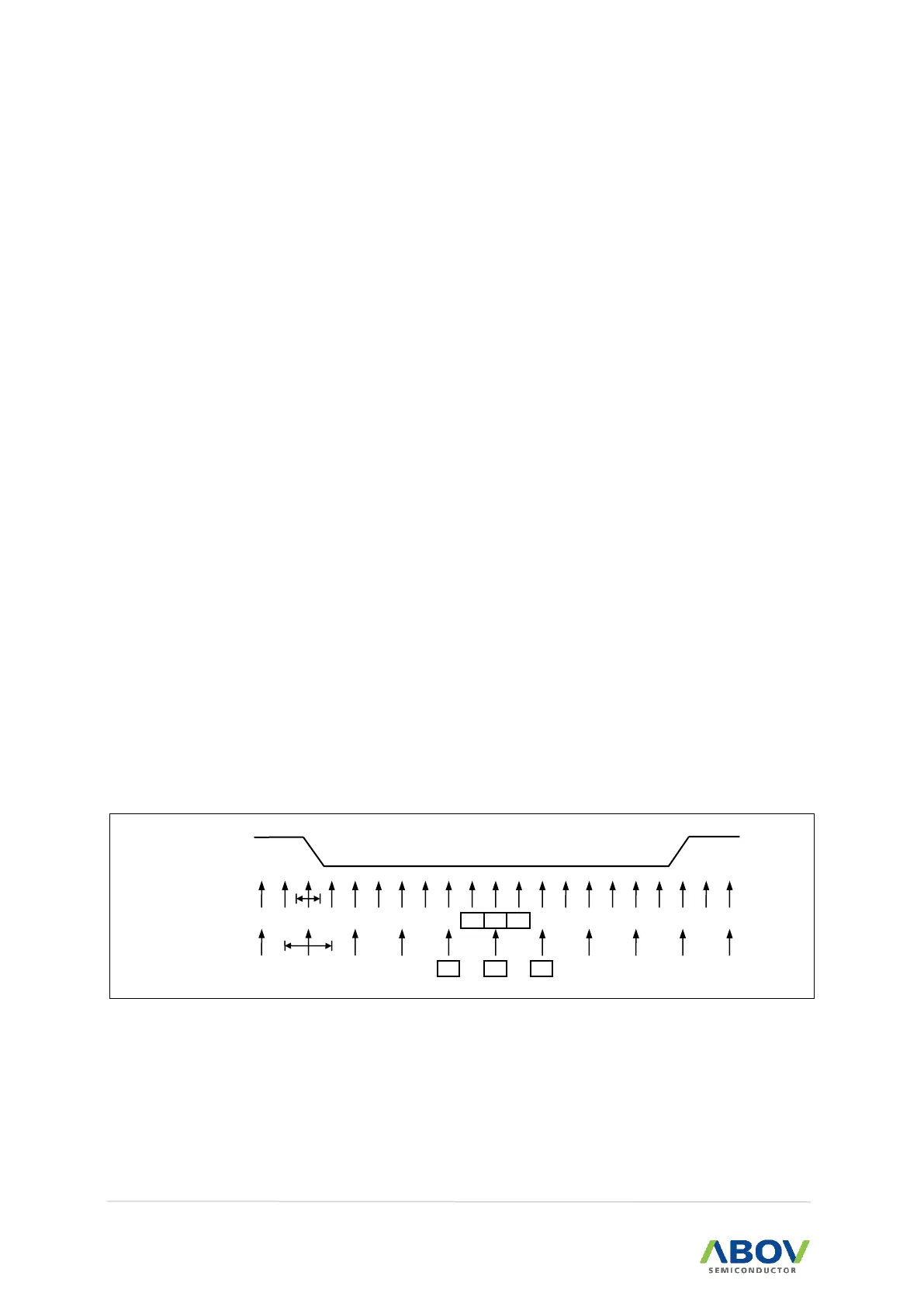
The next figure illustrates the sampling process of the start bit of an incoming frame. The sampling
rate is 16 times the baud-rate for normal mode, and 8 times the baud rate for Double Speed mode
(U2X=1). The horizontal arrows show the synchronization variation due to the asynchronous sampling
process. Note that larger time variation is shown when using the Double Speed mode.
Figure 74. Start Bit Sampling
When the Receiver is enabled (RXE=1), the clock recovery logic tries to find a high to low transition
on the RXDn line, the start bit condition. After detecting high to low transition on RXDn line, the clock
recovery logic uses samples 8, 9, and 10 for Normal mode, and samples 4, 5, and 6 for Double
Speed mode to decide if a valid start bit is received.