236 Firmware Version 6.0
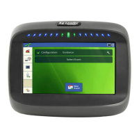
Control Valve Settings - PWM
• PWM Frequency
The frequency that the PWM control valve is
pulsed at. Settings can be found from the
manufacturer of the valve. Typical settings
range from 100-125 Hz.
Note: See PWM valve manufacturer information for recommended settings.
• PWM Gain
Determines how aggressively the control valve responds when making rate change adjustments. The
higher the value the more aggressive the system response is.
• Zero Flow Offset
Represents the maximum duty cycle that is sent to the control valve without producing any hydraulic flow
from the PWM valve. Using too high of a Zero Flow Offset value can cause the product control system to
not properly control low rates. See the PWM valve manufacturer information for recommended settings.
• PWM Standby
This is a user-defined setting that determines the percent duty cycle the system uses when the booms are
all off. The setting must be greater than the Zero Flow Offset.
Note: The current PWM Duty Cycle can be viewed at the Liquid Diagnostics screen. For more information,
see “Liquid Application Diagnostics” on page 246
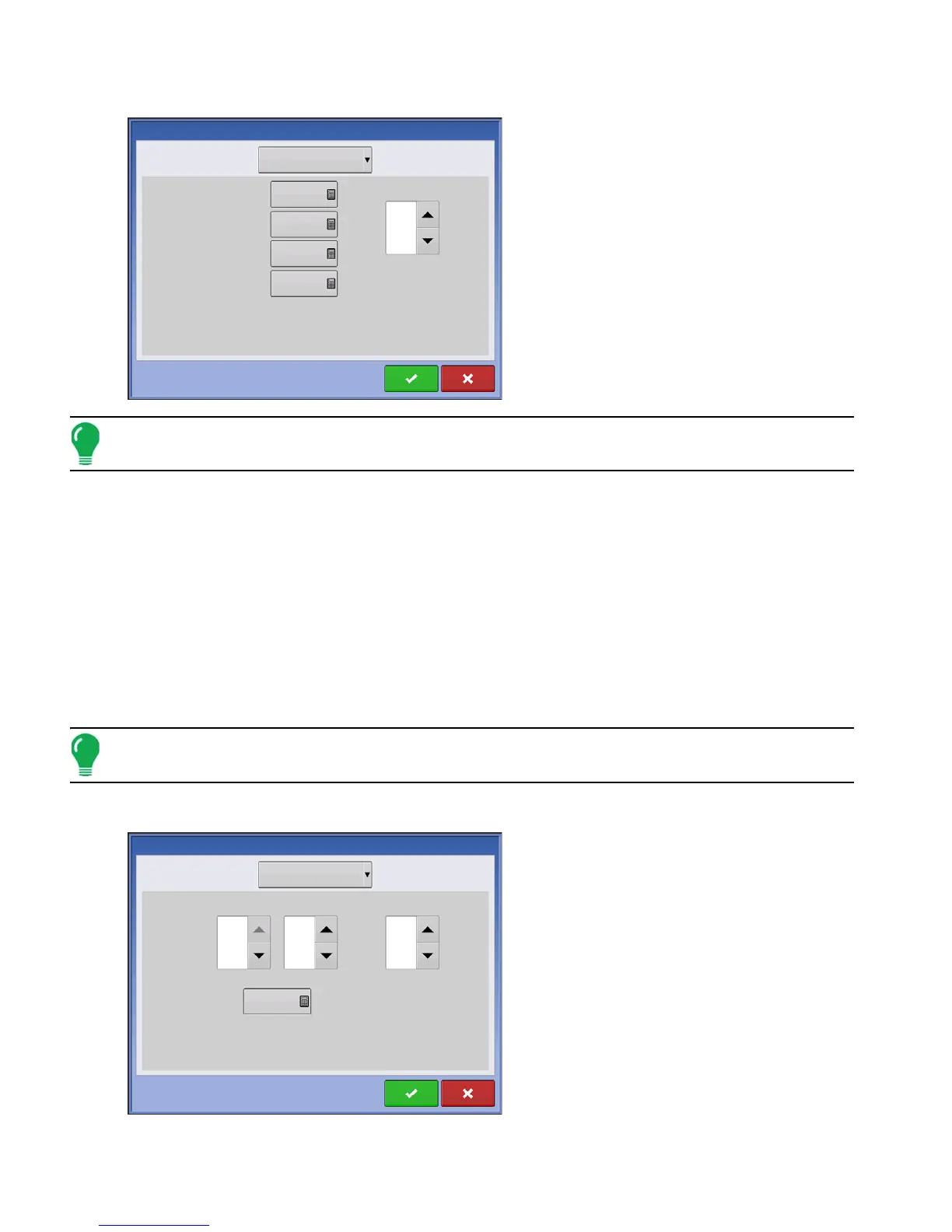
Control Valve Settings - Servo, Calibrated Reflow and Ramsey Valve
• Valve Response 1
Determines the speed of the servo valve when
product control error exceeds the Response
Threshold setting. The default for this setting is
100%. Decreasing the value will cause the servo
valve to run slower. Valve Response 1
represents the fast speed of the servo valve.
• Valve Response 2
Determines the speed of the servo valve when
product control error is less than the Response
Threshold setting. The default for this setting is
24%. Decreasing the value will cause the servo
valve to run slower. Valve Response 2
represents the slow speed of the servo valve.
Control Valve Settings
PWM 12 volt
Control Valve:
PWM Frequency
PWM Gain
Zero Flow Offset
PWM Standby
50
30
800
100
Allowable
Error
2 %
3 gal/min
Control Valve Settings
Control Valve:
Inline Servo
Valve
Response 1
Valve
Response 2
Response Threshold
100
24
Allowable
Error
2 %

 Loading...