136 1100 Series Nano Pump Service Manual
3 Repairing the Pump
7 If you have to exchange other parts, also, continue with that work first.
8 On the new board check the switch setting of address switch S1, see Table
51 on page 219.
9 Install the new board and reconnect the connectors. Make sure that the
board is fitted correctly in the board recess holes at the rear panel.
10 Replace the connector screws.
11 Replace foam and top covers, see “Replacing the Top Cover and Foam” on
page 154.
12 Reinstall the pump in the stack. Reconnect all cables. Turn on the nano
pump. If the status indicator turns red, continue with the section “Entering
An incorrect switch setting (e.g., TEST/BOOT) may cause the pump to turn into a basic
mode (yellow or red flashing status light). In such a case turn off the pump, re-set the
address switches, and turn on the pump again.
Make sure that P21 is not accidentally connected into the position of P16-P17 (possible on
revision A and B boards). This will damage the encoder of pump drive B when turned on.
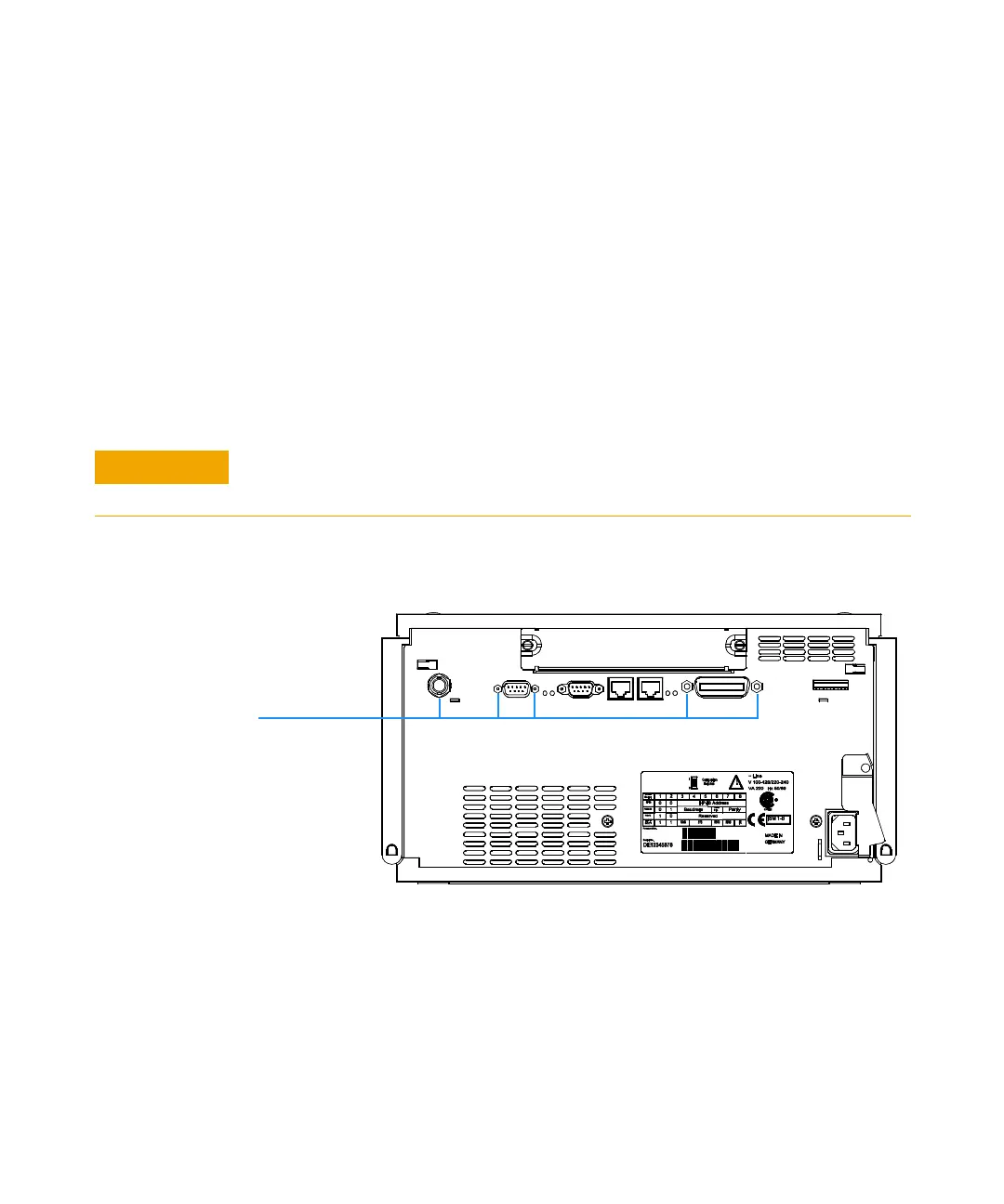
Figure 23 Rear of Nano Pump
Nut and
screws
 Loading...


