146
Interfacing
Setting the 8-Bit Configuration Switch
Setting the 8-Bit Configuration Switch
The 8-bit configuration switch is located next to the GPIB connector. Switch
settings provide configuration parameters for GPIB address, serial
comunication protocol and instrument specific initialization procedures
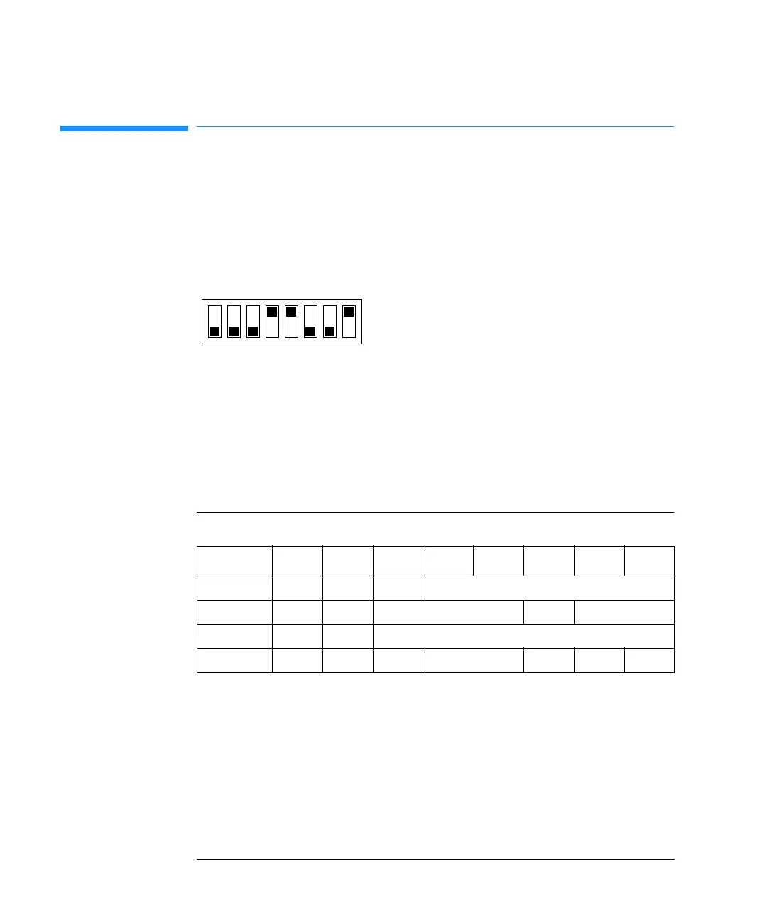
Figure 55 8-Bit Configuration Switch.
If you just want to change the GPIB address and need a detailed procedure,
refer to the Installing Your UV-Visible Spectroscopy System handbook.
Default GPIB address is set to 25 equal to a binary setting of 0 0 0 1 1 0 0 1
(where 0 means that the switch is down and 1 means that the switch is up;
the binary code of the address starts with the least significant bit at switch
number 8).
Switches 1 and 2 define which set of parameters (for example, for GPIB,
RS232 and so on) will be changed. Once the change has been completed, the
instrument must be powered up again in order to store the values in the
non-volatile memory.
In the non-volatile random access memory (NVRAM) the parameters are
kept, independantly if you turn the instrument off and on again. They will be
kept until the same set of parameters is subsequently changed and power is
1 2
3
4 5
6
7
8
Table 53 8-Bit Configuration Switch
Mode Select12345678
GPIB 0 0 GPIB Address
RS-232 0 1 Baudrate Data Bits Parity
Reserved 1 0 Reserved
TEST/BOOT 1 1 RSVD SYS RSVD RSVD FC

 Loading...


