General Power Meter Functions 2
N1911A/1912A P-Series Power Meters User’s Guide 103
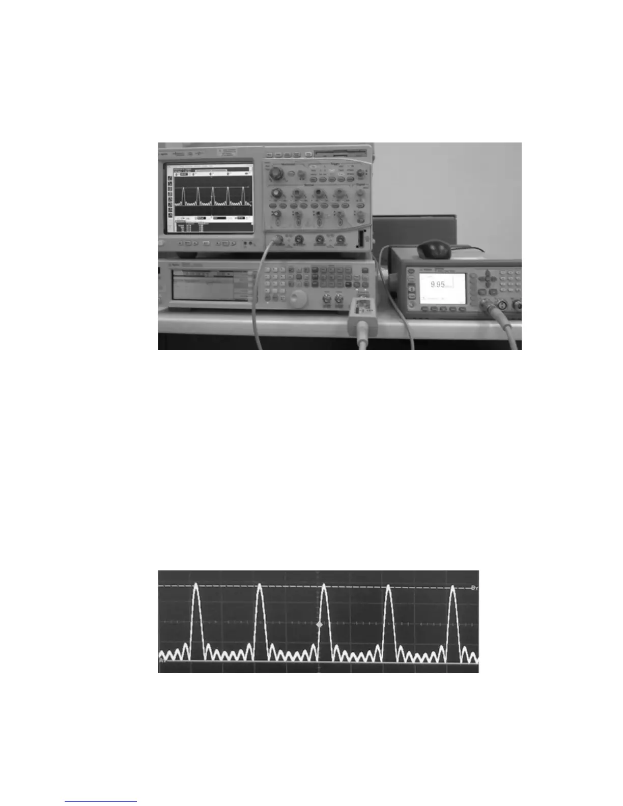
Figure 2-81 Measurement example for Option H02
Measurement example for Option H02
For this example, N1912A P- Series power sensors, MXG N5182A signal
generator, and Infiniium 54832D oscilloscope will be used.
1 Connect the power sensor input to the RF input of the signal generator.
2 Connect the video output of the power meter (Option H02) to the
channel 1 of the oscilloscope with a BNC cable.
3 Generate an RF Multitone waveform from the signal generator.
4 Set the oscilloscope to Auto Trigger mode to capture the waveform.
Figure 2-82 Example screenshot of the RF Multitone waveform

 Loading...


