Using P-Series Power Sensor 3
N1911A/1912A P-Series Power Meters User’s Guide 125
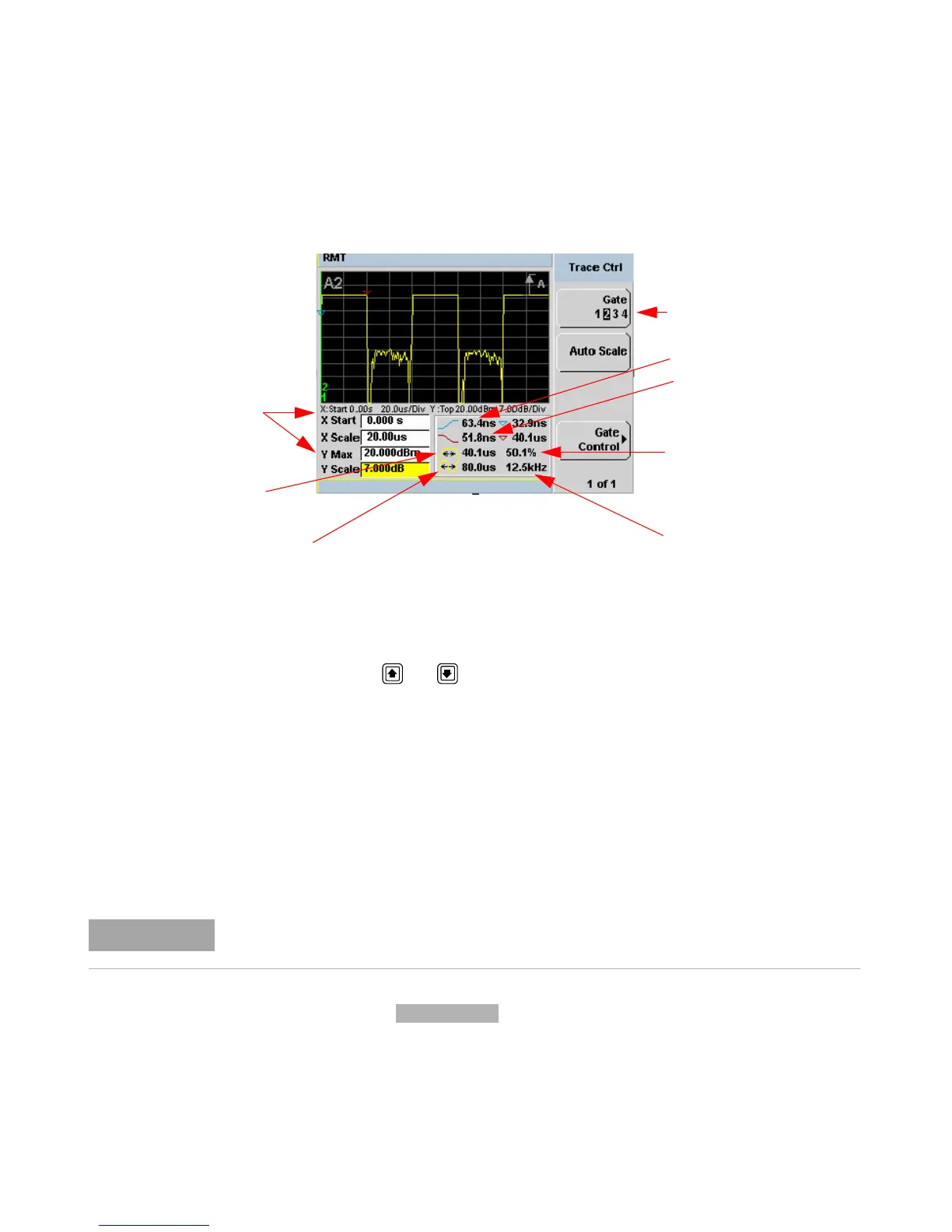
Figure 3-97 Trace display with trace control menu
The fields on the lower left of the screen are the X and Y trace setup
fields. Using the or keys you can highlight the item and change its
value. (See Figure 3- 97)
The table on the lower right of the screen shows the eight automatic time
measurements performed on the first complete captured pulse after the
trigger. The eight measurements are rise time, fall time, time to positive
occurrence, time to negative occurrence, pulse width, pulse period (pulse
repetitive interval), pulse repetitive frequency and duty cycle.
The current settings of the X and Y scale are displayed on the reporting
line above both tables.
Gate Control Press to display the Gate Ctrl menu. Setting the
gate features are described in greater details in “Gate Control in a Single
Enlarged Window” on page 122”.
Trace Setting
Rising Edge
Gate 2 Active
Duty Cycle
Pulse Repetitive Frequency
Pulse Width
Pulse Period
Falling Edge
If you want to view the trace in linear mode, the Trace Setup is the only location where you
can change the Y-scale units from
dBm to Watts; otherwise the default unit is in logarithmic.