1 Introduction
10 N1911A/1912A P-Series Power Meters User’s Guide
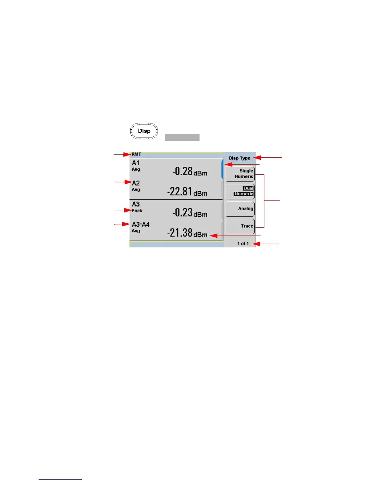
The Display Layout
Figure 1- 1 shows the display layout when two windows are configured in
dual numeric mode.
Pressing , the other display formats are available.
Figure 1-1 Dual numeric display
1 The status reporting line displays messages and the control status of
the power meter. For example, the status can be either RMT (remote,
GPIB, USB or LAN operation) or LCL (local, front panel operation).
The message fields indicate ERR for any error conditions that occur or
informing you to Please Zero the power sensor.
2 The blue highlight on the right hand side of the window shows it is the
currently selected measurement display line. This measurement line is
the Upper Window/Upper Measurement.
3 The measured channel is shown. With a P- Series or an E- Series E9320
power sensor connected, and channel in trigger mode, the associated
gate number is shown.
4 The associated measurement type is shown below the channel and gate
number.
 Loading...


