2 General Power Meter Functions
86 N1911A/1912A P-Series Power Meters User’s Guide
Setting Measurement Limits
You can configure the power meter to detect when a measurement has
crossed over a predefined upper and/or lower limit value.
Limits are boundaries set for a certain power range and it can be applied
to power, ratio or difference measurement.
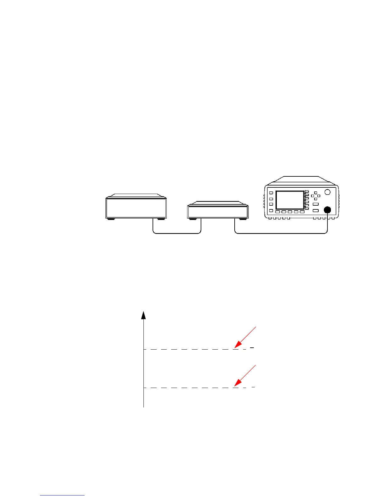
Figure 2-63 Limits checking applications
In this application a swept frequency signal is applied to the input of the
Device Under Test. The power meter measures the output power. The
limits have been set at +4 dBm and +10 dBm. A fail occurs each time the
output power is outside these limits as shown in Figure 2- 64.
Figure 2-64 Limits checking results
Power Meter
Swept Source
OUT
OUT
Device
Under Test
+4 dBm
+10 dBm
Amplitude
F
o
o
o
o
o
o
o
Fail
Fail
Upper Limit Line
Lower Limit Line

 Loading...


