8 Using N8480 Series Power Sensors
210 N1911A/1912A P-Series Power Meters User’s Guide
3 Press to complete the selection of the calibration factor table.
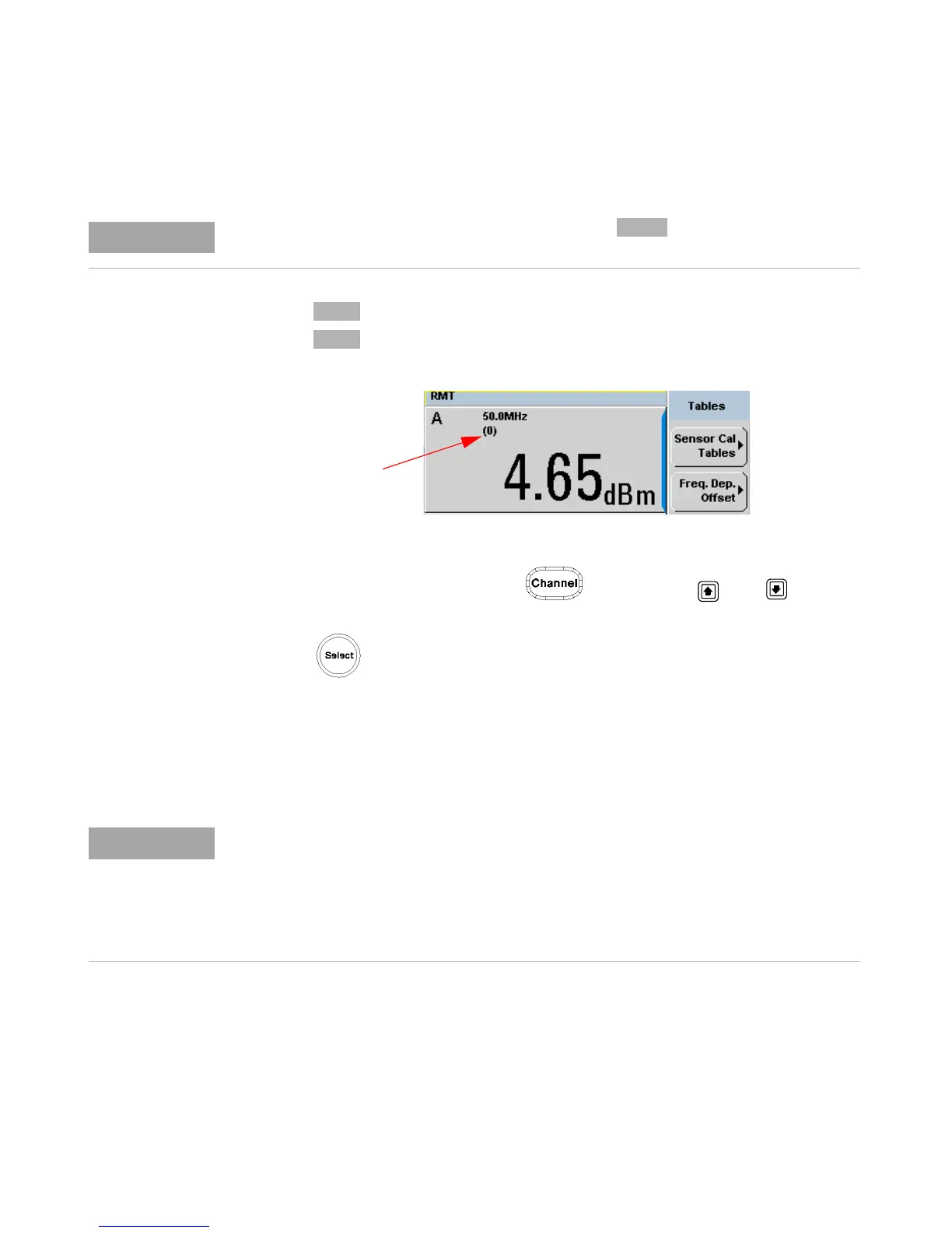
4 Press again to display the measurement screen. Figure 8- 142
shows which offset table is selected.
Figure 8-142Frequency dependent offset indicator
5 To change the frequency, press and use the and keys to
highlight the Frequency field.
6 Press to display the Frequency pop- up window. Use the numeric
keypad to enter the required value in the Frequency pop- up window.
7 To confirm your choice, press the appropriate unit softkey.
8 Connect the power sensor to the signal to be measured.
9 The corrected measurement result is now displayed.
When no data is contained in the highlighted table, the key is disabled (grayed out).
If the measurement frequency does not correspond directly to a frequency in the sensor
calibration table, the power meter calculates the calibration factor using linear
interpolation.
If you enter a frequency outside the frequency range defined in the sensor calibration table,
the power meter uses the highest or lowest frequency point in the sensor calibration table
to set the calibration factor.

 Loading...


