1 Introduction
12 N1911A/1912A P-Series Power Meters User’s Guide
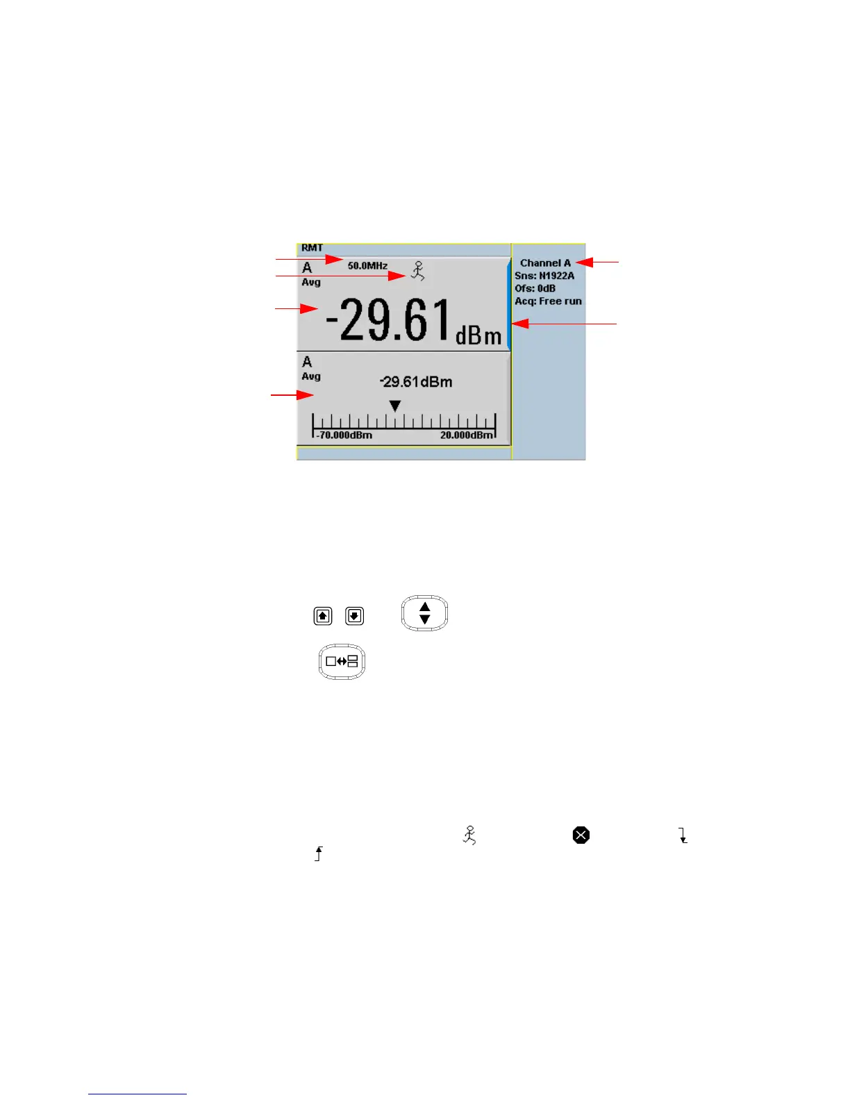
Figure 1-2 Single numeric and analog display
10 Figure 1- 2 shows the default display mode of two measurement
windows. The upper measurement window has a blue highlight on the
right hand side of the window showing it has been selected.
Using the , , or keys you can change the selection of the
measurement window.
Using the key on numeric measurement results window you
can choose either two rectangular windows, a single enlarged window,
or a full screen display by pressing. The display style is applied to the
currently selected window or measurement line.
11 The upper window is configured to show a single numeric display.
12 The lower window is configured to show an analog meter which
displays the measurement result and the meter scaling.
13 With a P- Series or an E- Series E9320 power sensor connected, the
symbol shows the trigger state (Free Run), (Stopped), (Negative
Slope), or (Positive Slope).
14 The channel measurement frequency.
15 This displays the connected sensor, the offset value, and the acquisition
mode on the channel. On dual channel models it shows for both
channels.
 Loading...


