4 Using E9320 E-Series Power Sensors
142 N1911A/1912A P-Series Power Meters User’s Guide
After you have completed this initial set up, you can, if required, return to
the following setup to improve your measurement results:
•The Channel Setup to configure any averaging and offsets.
•The Trigger setup to configure any additional setting there.
•The Meas Setup to configure any additional setting there.
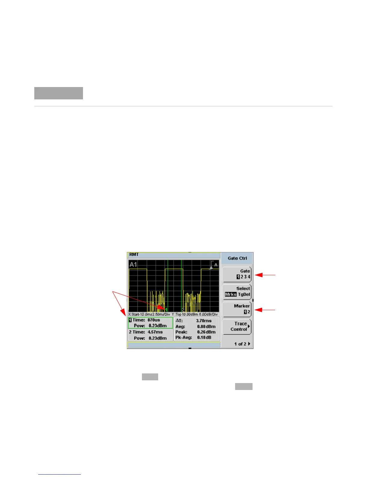
Gate Control in a Single Enlarged Window
When you initially display a single enlarged window, the Gate Control menu
is available. Setting the gate features are described in greater detail in
“Setting Measurement Channel Gates” on page 57. However, the following
sections are to give you an overview of the control and their impact on
the displayed results.
Figure 4-107Trace display with gate control menu
Gate Pressing scrolls through the 4 gates available for each channel.
The gate displayed is highlighted below the softkey. It is also
displayed in the channel/gate annotation in the top left of the screen.
If the bandwidth of a modulated signal is unknown, you may discover that during the set up
process, a power sensor of lesser or greater bandwidth is required.
Gate 1 Active
Marker 1 Active
Active Marker
 Loading...


