Using E9320 E-Series Power Sensors 4
N1911A/1912A P-Series Power Meters User’s Guide 143
Select Pressing displays the gate markers or trigger
markers.
Markers When is selected, Markers 1 and 2 indicate the start and
end points of the selected measurement gate. Pressing toggles
between the two markers, the highlighted marker is the currently active
marker. Use the and keys to move the markers left or right across
the display.
The tables on the lower left of the screen show the time (
Time:) and the
instantaneous power level (
Pow:) of the markers at their configured points.
The table highlighted with the green border represents the active marker,
also highlighted in green. A negative time value indicates a measurement
before the trigger point. (See Figure 4- 107).
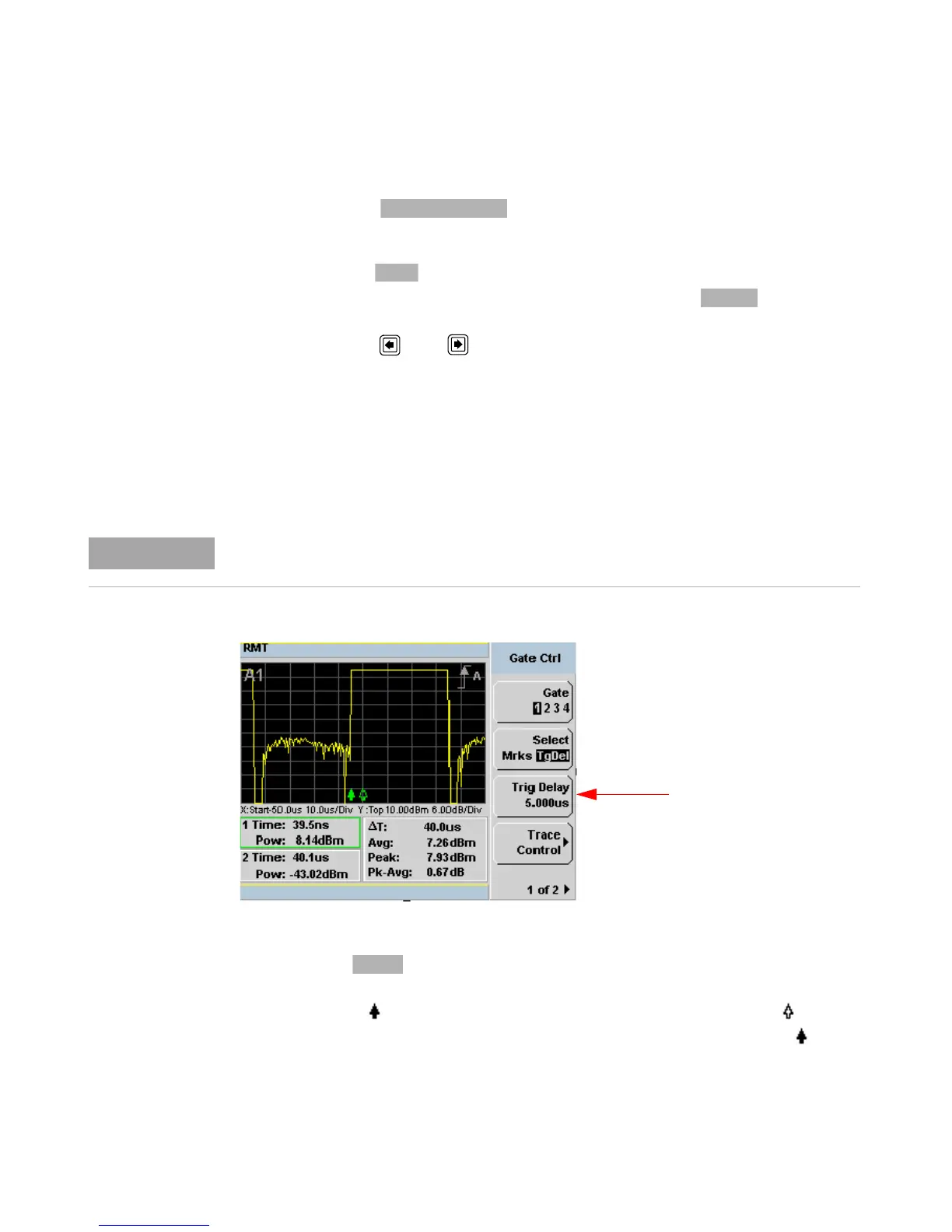
Figure 4-108Trace display with trigger delay menu
TgD el When is selected you can adjust the trigger delay. The
display changes to remove the gate markers and displays the trigger
marker(s). The indicates when the trigger event occurs, whilst shows
the delayed trigger point. When the two points coincide, only the
trigger is shown.
Gate timing parameters are all related to your chosen trigger point. This may be different
from the timing of the triggering event if you have configured a trigger delay.

 Loading...


