2 General Power Meter Functions
58 N1911A/1912A P-Series Power Meters User’s Guide
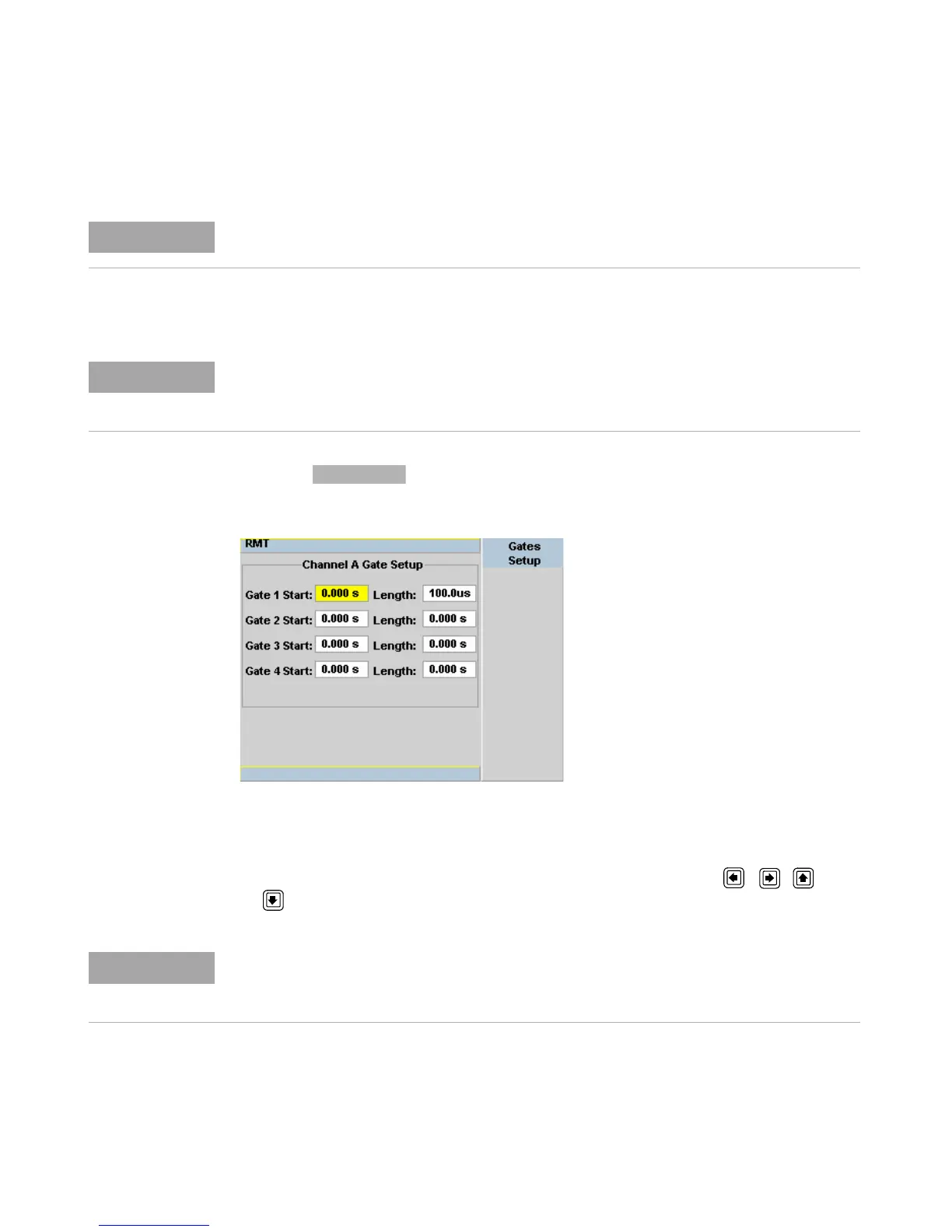
Procedure
• Press . The Channel Gate Setup screen is displayed.
Figure 2-38 Gate Setup screen
1 Highlight the Gate Start you want to configure using the , , and
keys.
Figure 2-37 shows measurement results using this example of the gates placement.
This procedure uses the Gates Setup under the Channel Setup menu. Alternatively, you
can use a more visual method, when in the Graphical Trace Mode (Gate Control Menu), to
set the channel’s Gate Control. (See “Setting the Trace Display” on page 118).
The gate start time is relative to the trigger event. Positive values set a measurement gate,
to a maximum time of 1 second, after the trigger. Negative time gate start values set a
measurement gate, to a maximum time of 1 second, before the trigger.
 Loading...


