Home
Agilent Technologies
Measuring Instruments
N1911A
Agilent Technologies N1911A User Manual
4
of 1
of 1 rating
297 pages
Give review
Manual
Specs
To Next Page
To Next Page
To Previous Page
To Previous Page
Loading...
viii
N1911/1912A P-S
eries Power Meters User’s Guide
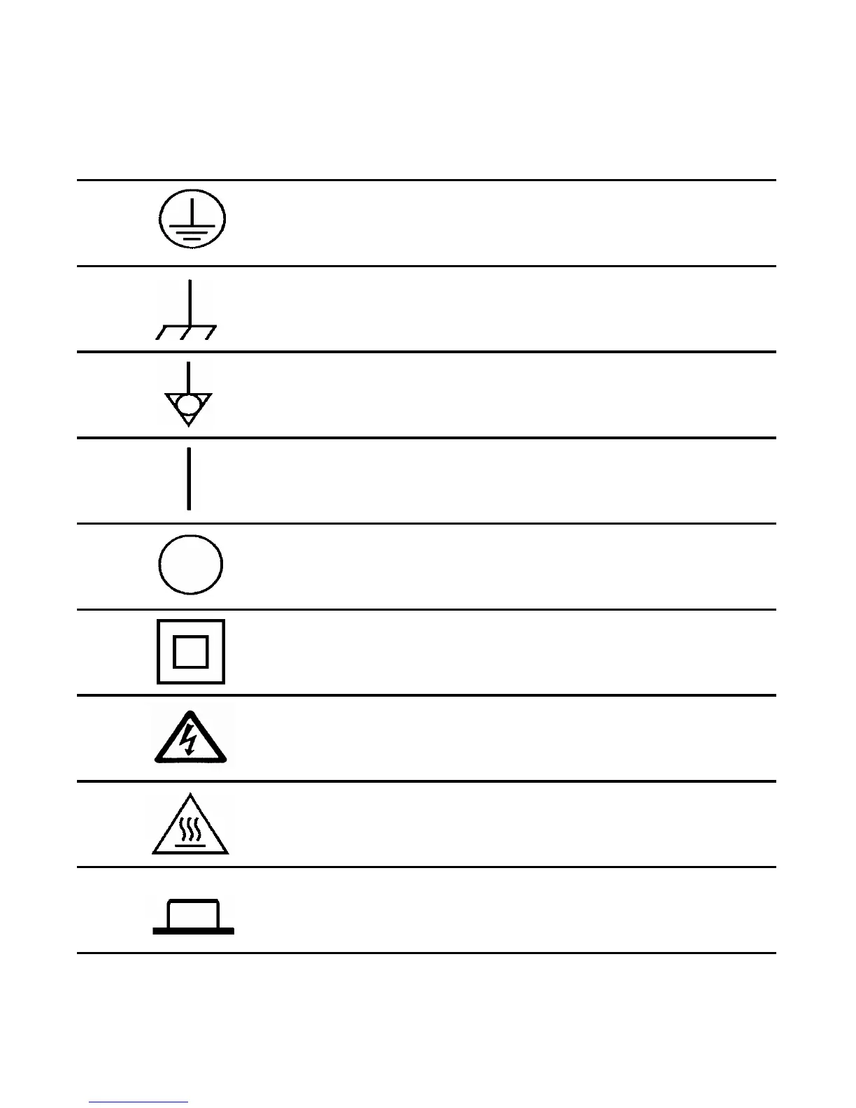
PROTECTIVE CONDUCTOR TERMINAL.
Frame or chasis TERMINAL.
Equipotentiality
.
On (Supply).
Off (Supply).
Equipment protected througho
ut
by DOUBLE INSULA
TION or
REINFORCED INSULA
TI
ON.
Caution, risk o
f electric shock.
Caution,
hot surface.
In position of bi-stable push control.
7
9
Table of Contents
Default Chapter
3
Certification
3
General Warranty
3
Warranty Service
3
Limitation of Warranty
4
Exclusive Remedies
4
Restricted Rights Legend
5
Technology Licenses
5
Safety Summary
6
Recommended Calibration Interval
6
Safety Symbols
7
General Safety Information
10
Environmental Conditions
11
Regulatory Information
11
Regulatory Markings
12
Declaration of Conformity (Doc)
13
In this Guide
14
Table of Contents
15
1 Introduction
28
LXI Class-C Compliant Power Meter
28
Rack Mounting
28
Power Meter and Sensor Capability
29
Conventions Used in this Guide
30
Front Panel Keys and Connections
31
The Display Layout
36
Figure 1-1 Dual Numeric Display
36
Figure 1-2 Single Numeric and Analog Display
38
Figure 1-3 Full Screen Numeric Display
39
Figure 1-4 Trace Display in both Windows
40
Figure 1-5 Trace Display in Single Enlarged Window in Markers Mode
41
Figure 1-6 Trace Display in Single Enlarged Window in Trigger Delay Mode
42
Figure 1-7 Trace Display in Single Enlarged Window in Trace Control Mode
43
Window Symbols and Pop-Ups
44
Using the Instrument Web Browser
48
Figure 1-8 Opening the Instrument Web Interface
48
Figure 1-9 N1912A P-Series Power Meter Web Browser (Welcome Page)
49
Figure 1-10 Status Message before Toggle ID Is Selected
50
Figure 1-11 Status Message When Toggle ID Is Selected
50
Figure 1-12 Example of Lan Status Message
51
Table 1-1 Type of Lan Status Message
51
Figure 1-13 Viewing LAN Configuration Settings from the Web Interface
52
Figure 1-14 Password Security Dialog Box
53
Figure 1-15 Changing the Instrument LAN Interface Configuration
54
2 General Power Meter Functions
56
Setting the Units of Measurement
56
Table 2-2 Measurement Units - Single Channel Meters
56
Table 2-3 Measurement Units - Dual Channel Meters
56
Setting the Measurement Frequency
58
Figure 2-16 Frequency Pop-Up
58
Setting the Resolution
59
Making Relative Measurements
60
Figure 2-17 Typical Relative Measurement Display
60
Figure 2-18 Numeric Display
61
Setting the Pulse Reference Levels
62
Figure 2-19 Measurement Configuration Screen
62
Figure 2-20 Pulse Duration Measurement between Two Reference Levels
63
Figure 2-21 Trace Ref Lvl 1 Pop-Up
63
Figure 2-22 Trace Ref Lvl 2 Pop-Up
64
Figure 2-23 Pulse Duration Ref Lvl Pop-Up
64
Setting Offsets
65
Figure 2-24 Simplified Measurement Path
65
Figure 2-25 Typical Channel Offset Display
66
Figure 2-26 Channel Offset Indicator
67
Figure 2-27 Typical Display Offset Display
68
Figure 2-28 Frequency Dependent Offset Tables Display
70
Figure 2-29 Frequency Dependent Offset Indicator
71
Figure 2-30 "Edit Offset" Display with Data Added
72
Figure 2-31 Edit Table Title Pop-Up
73
Setting Measurement Averaging
75
Figure 2-32 Typical Averaged Readings
75
Figure 2-33 Meas Avg Count Pop-Up
76
Step Detection
77
Setting the Video Averaging
78
Figure 2-34 Video Avg Count Pop-Up
79
Setting the Video Bandwidth
80
Table 2-4 P-Series Sensor Video Bandwidth Setting
80
Figure 2-35 Bandwidth Filter Shapes
81
Figure 2-36 Video Bandwidth Pop-Up
82
Setting Measurement Channel Gates
83
Figure 2-37 Example of Measurement Gates
83
Figure 2-38 Gate Setup Screen
84
Figure 2-39 Time Gating Start Pop-Up
85
Figure 2-40 Time Gating Length Pop-Up
85
Figure 2-41 Auto Gate Settings Display
86
Figure 2-42 Marker 1 Ref Percentage Pop-Up
86
Figure 2-43 Marker 2 Ref Percentage Pop-Up
87
Figure 2-44 the Placement of Gates (Markers) in Auto Gating Mode
87
Setting up the Channel Trace
88
Figure 2-45 Trace Setup Display
88
Figure 2-46 Trace Start Time Pop-Up
89
Figure 2-47 X Scale/Division Pop-Up
89
Figure 2-48 Trace Units Pop-Up
90
Figure 2-49 y Scale Maximum Value Pop-Up
90
Figure 2-50 y Scale/Division Pop-Up
91
Setting the Trigger
92
Figure 2-51 Trigger Menu - Free Run Mode
92
Figure 2-52 Trigger Setting Menu 1
93
Figure 2-53 Trigger Level Pop-Up
94
Figure 2-54 Trigger Delay Pop-Up
95
Figure 2-55 Trigger Setting Menu 2
95
Figure 2-56 Trigger Holdoff Pop-Up
96
Figure 2-57 Trigger Hysteresis Pop-Up
97
Setting External Trigger for Normal and Average Power Measurement
98
Table 2-5 Power and Frequency Sweep Mode Compatibility Table
98
Table 2-6 Power and Frequency Sweep Measurement Functions Table
99
Figure 2-58 TRIG in and TRIG out Connection Diagram between Power Meter and
100
Power Source
100
Figure 2-59 Channel Setup Display
100
Figure 2-60 Sensor Mode Pop-Up
101
Figure 2-61 Trigger Setting Menu 1
102
Figure 2-62 Trigger Setting Menu 2
102
Figure 2-63 Limits Checking Applications
112
Figure 2-64 Limits Checking Results
112
Setting Measurement Limits
112
Table 2-7 Range of Values for Window Limits
113
Figure 2-65 Minimum Limit Pop-Up
114
Figure 2-66 Limit Failures
115
Figure 2-67 Sixteen Measurements Per Channel
116
Setting the Measurement Display
116
Figure 2-68 Measurement Feed Example
117
Figure 2-69 Measurement Setup Showing Single Configuration
118
Figure 2-70 Function Pop-Up
119
Figure 2-71 Measurement Type Pop-Up
119
Figure 2-72 Gating Number Pop-Up
120
Figure 2-73 Measurement Setup Showing Combined Configuration
121
Figure 2-74 Measurement Example Display
122
Figure 2-75 Maximum Limit Pop-Up
123
Figure 2-76 Minimum Limit Pop-Up
123
Scaling the Analog Display
123
Figure 2-77 Increment and Decrement Multiplier
124
Recorder Output
125
Figure 2-78 Recorder Minimum Pop-Up
126
Figure 2-79 Recorder Maximum Pop-Up
126
Table 2-8 Ranges of Recorder Output Setting
127
Figure 2-80 Increment and Decrement Multiplier
128
Figure 2-83 Save/Recall Screen
130
Saving and Recalling Power Meter States
130
Figure 2-84 Save Confirm Pop-Up
131
Figure 2-85 File Name Pop-Up
131
Figure 2-86 Recall Pop-Up
132
Figure 2-87 Zeroing Pop-Up
133
Zeroing and Calibrating the P-Series Sensor
133
Figure 2-88 Calibration Wait Pop-Up
134
Figure 2-89 Please Zero and Calibrate Window
136
Figure 2-90 Preset Display Options
137
Presetting the Power Meter
137
Table 2-9 Preset Compatibility Matrix for E-Series E9320 Power Sensor
138
Setting the Cable Short/Long
139
3 Using P-Series Power Sensor
141
Introduction
142
Configuring a Power Measurement
143
Setting the Trace Display
144
Figure 3-92 P-Series Sensor Default Channel Setup
145
Figure 3-93 Trace Display in Dual Channel Power Meter
146
Figure 3-94 Trace Display in Single Enlarged Window
147
Figure 3-95 Trace Display with Gate Control Menu
148
Figure 3-96 Trace Display with Trigger Delay Menu
149
Figure 3-97 Trace Display with Trace Control Menu
151
Figure 3-98 Trace Display in Full Screen
152
Figure 3-99 P-Series Power Sensor Default Channel Setup
153
Figure 3-100Channel Offset Display
154
4 Using E9320 E-Series Power Sensors
158
Introduction
158
Table 4-10 Sensor Bandwidth
158
Figure 4-101 Bandwidth Filter Shapes
159
Power Meter Configuration
160
Figure 4-102 E-Series E9320 Power Sensor Default Channel Setup
160
Configuring a Peak Power Measurement
161
Measurement Accuracy
162
Setting the Trace Display
164
Figure 4-104 E-Series E9320 Power Sensor Channel Setup When Trigger Is Selected
166
Figure 4-105Trace Display in Dual Channel Power Meter
166
Figure 4-106Trace Display in Single Enlarged Window
167
Figure 4-107Trace Display with Gate Control Menu
168
Figure 4-108Trace Display with Trigger Delay Menu
169
Figure 4-109Trace Display with Trace Control Menu
171
Figure 4-110Trace Display in Full Screen
172
Figure 4-111E-Series E9320 Power Sensor Dafault Channel Setup
173
Figure 4-112Channel Offset Display
174
Introduction
178
5 Using E9300 E-Series Power Sensors
179
Power Meter Configuration
179
Figure 5-113E9300 E-Series Auto-Averaging Settings
179
Figure 5-114 E9300 E-Series Sensor Default Channel Setup
180
Measurement Accuracy
181
Table 5-11 Power Sensor Connection Requirements
181
Figure 5-115Frequency Pop-Up
182
Measuring Spread Spectrum and Multitone Signals
183
Figure 5-116Spread Spectrum Signal
183
Figure 5-117 Wideband CDMA Error of E-Series E9300 Power Sensor Versus Corrected
184
Figure 5-118CDMA (IS-95A): 9Ch Fwd
184
Figure 5-119Calibration Factors Versus Frequency
185
Measuring TDMA Signals
186
Electromagnetic Compatibility (EMC) Measurements
188
Measurement Accuracy and Speed
189
6 Using E4410 E-Series Power Sensors
194
Introduction
194
Power Meter Configuration
195
Figure 6-120E-Series CW Sensor Auto-Averaging Settings
195
Figure 6-121E-Series E4410 Sensor Default Channel Setup
196
Measurement Accuracy
197
Figure 6-122Frequency Pop-Up
198
7 Using 8480 Series Power Sensors
200
Introduction
200
Power Meter Configuration
201
Figure 7-1238480 Series Auto-Averaging Settings
201
Figure 7-1248480 Series Sensor Default Channel Setup
202
Table 7-12 8480 Series Connection Requirements
203
Measurement Accuracy
205
Frequency Specific Calibration Factors
206
Figure 7-125Reference Calibration Factor Pop-Up Window
207
Figure 7-126Calibration Factor Pop-Up Window
208
Figure 7-127Calibration Factor Display
208
Sensor Calibration Tables
210
Figure 7-128Sensor Table Selected
211
Figure 7-129Frequency Dependent Offset Indicator
211
Figure 7-130Frequency/Calibration Table Display
212
Table 7-13 Installed Power Sensor Models
213
Figure 7-131"Sensor Tbls" Screen
214
Figure 7-132"Edit Cal" Display
215
Figure 7-133Edit Table Title Pop-Up
215
8 Using N8480 Series Power Sensors
222
Introduction
222
Table 8-14 Power Range in the Range Setting
222
Power Meter Configuration Changes
224
Figure 8-134Auto-Averaging Settings
224
Default Channel Setup
225
Figure 8-135N8480 Series Sensor (Excluding Option CFT) Default Channel Setup
225
N8480 Series Sensors Connection Requirements
226
Table 8-15 N8480 Series Connection Requirements
226
N8480 Series Power Sensors (Excluding Option CFT)
227
Figure 8-137Frequency Pop-Up
228
N8480 Series Power Sensors with Option CFT
229
Figure 8-138Reference Calibration Factor Pop-Up Window
230
Figure 8-139Calibration Factor Pop-Up Window
231
Figure 8-140Calibration Factor Displayed
232
Figure 8-141Sensor Table Selected
235
Figure 8-142Frequency Dependent Offset Indicator
236
Figure 8-143Frequency/Calibration Table Display
237
Table 8-16 Installed Power Sensor Models
238
Figure 8-144"Sensor Tbls" Screen
239
Figure 8-145"Edit Cal" Display
240
Figure 8-146Edit Table Title Pop-Up
240
9 Complementary Cumulative Distribution Function (CCDF)
243
Introduction
244
Setting the CCDF Table
245
Figure 9-147CCDF Table in Windowed Display
245
Figure 9-148CCDF Table in Expanded Display
246
Figure 9-149CCDF Table in Full-Screen Display
247
Setting the CCDF Trace
248
Figure 9-150Trace Display Select Control Menu
248
Figure 9-151CCDF Trace Display with Marker Trace Menu
249
Figure 9-152Scale/DIV Pop-Up
251
Figure 9-153Selection of CCDF Trace to be Stored as a Reference Trace
252
10 Maintenance
253
Self Test
254
Figure 10-154Self Test Complete
255
Test Descriptions
256
Error Messages
258
Figure 10-155Error Indicator Position
258
Error Message List
260
Operator Maintenance
269
Figure 10-156Replacing the Fuse
270
Contacting Agilent Technologies
271
Erasing Memory Data
274
Figure 10-157Secure Erase Status Pop-Up
274
Returning Your Power Meter for Service
275
Agilent Sales and Service Offices
277
11 Specifications and Characteristics
280
Introduction
280
Power Meter Specifications
282
Remote Programming
284
Measurement Characteristics
285
Figure 11-158Measured Rise Time Percentage Error Versus Signal under Test Rise Time
287
Rear Panel Inputs and Output Connections
288
Mw Power Reference
289
Environmental Conditions
290
Physical Characteristics
291
Regulatory Information
292
System Specifications and Characteristics
293
Figure 11-159P-Series Sensor Error in Peak-To-Average Measurements for a Two-Tone Input
294
Other manuals for Agilent Technologies N1911A
Programming Guide
803 pages
Configuration Guide
5 pages
4
Based on 1 rating
Ask a question
Give review
Questions and Answers:
Need help?
Do you have a question about the Agilent Technologies N1911A and is the answer not in the manual?
Ask a question
Agilent Technologies N1911A Specifications
General
Brand
Agilent Technologies
Model
N1911A
Category
Measuring Instruments
Language
English
Related product manuals
Agilent Technologies N1913a
263 pages
Agilent Technologies N1914a
263 pages
Agilent Technologies N1996A-503
366 pages
Agilent Technologies N5230C
282 pages
Agilent Technologies N5242A
342 pages
Agilent Technologies N9020A
107 pages
Agilent Technologies N5230A
262 pages
Agilent Technologies N9342C
179 pages
Agilent Technologies N9344C
179 pages
Agilent Technologies EXA N9010A
175 pages
FieldFox N9912A
209 pages
FieldFox N9913A
219 pages