3-17 PIM/Interference (Option 24) Spectrum Analyzer Measurements
3-82 PN: 10580-00447 Rev. H Spectrum Analyzer MG
3-17 PIM/Interference (Option 24)
To select PIM/Interference measurement go to main menu and press MEASURE > MEASUREMENT
>PIM/Interference. The PIM/interference measurement is set up using the “SETUP Menu (PIM/Interference)”
on page 3-85. The interference finder measurement is used in conjunction with a directional antenna to locate
the direction of an interfering signal. This test measures the integrated power of a received signal over a
specified frequency range. During the measurement, the instrument emits an audio tone that coincides with
the power of the received signal. As the antenna is pointed toward the signal source, the signal level increases
further into the set MAX and MIN level, and the audio increases in pitch. An example of a frequency
modulated interfering signal is shown in the figure below.
Frequency and level settings for many interfering signals can be set as follows:
1. Select MEASURE on the main menu.
2. Select Interference from the MEASUREMENT button.
3. Select SETUP and then do the following:
• Set the signal INTEGRATION BW (bandwidth).
• Toggle and set the POWER LIMIT if you wish to see pass/fail test results.
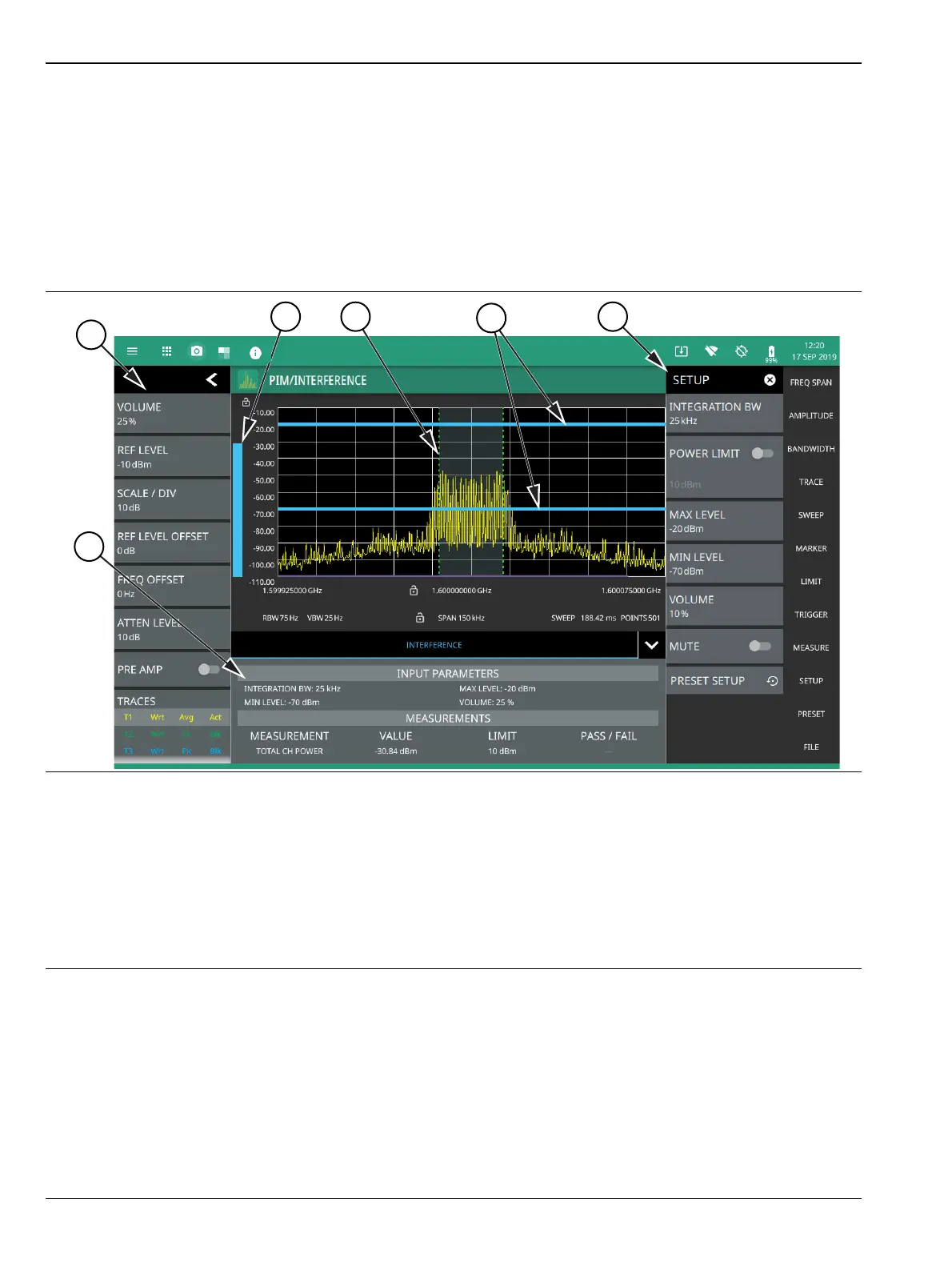
1. The status panel provides quick access to common spectrum analyzer settings. See “STATUS PANEL
(PIM/Interference)” on page 3-84.
2. A vertical bar corresponds to the received signal strength within the integration bandwidth.
3. Dashed vertical lines and a shaded region define the received channel integration bandwidth.
4. Horizontal blue lines define the audio response range for the measurement.
5. All signal power measurement parameters are set via the SETUP menu. See “SETUP Menu (PIM/Interference)”
on page 3-85.
6. Interference setup parameters and measurement results are shown in a table at the bottom of the display.
Figure 3-68. PIM/Interference Measurement