2-4 Status Panel Spectrum Analyzer Overview
2-6 PN: 10580-00447 Rev. H Spectrum Analyzer MG
2-4 Status Panel
The status panels and features illustrated in this section are unique to the spectrum analyzer and to the
particular measurement and view that is selected. Below is the spectrum analyzer status panel with the
corresponding minimized status panel icons, that covers basic spectrum, spectrogram, channel power, occupied
bandwidth (OBW), adjacent channel power (ACP), and spectral emission mask (SEM) measurements (selected
via MEASURE > MEASUREMENTS menu).
Refer to Chapter 3 for SPA measurement setup.
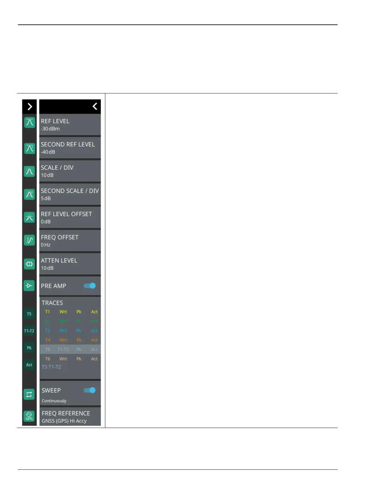
REF LEVEL: Sets the reference level of the top graticule line in the selected units.
If the reference level offset is not zero, OFFSET REF LEVEL is displayed at this
location. Refer to Section 3-4 “Setting Amplitude Parameters” on page 3-8.
SECOND REF LEVEL: The reference level is the top graticule line to the right on
the measurement display. Its functionality is exactly same as reference level, but it
is only available when trace math is enabled.
SCALE/DIV: Sets the graticule scale/division for log-based units. This setting does
not apply to linear units
SECOND SCALE/DIV: It applies to second reference level and is available only
when trace math is enabled.
REF LEVEL OFFSET: Sets the reference level offset in dB units. This setting can
compensate for the presence of external input attenuation or gain.
FREQ OFFSET: Accounts for frequency conversions outside of the analyzer.
Refer to Section 3-3 “Setting Frequency Parameters” on page 3-2.
ATTEN LEVEL: When auto attenuation is off, sets input attenuation.
PRE AMP: Toggles the low-noise front-end preamplifier on or off. Refer to
Section 3-4 “Setting Amplitude Parameters” on page 3-8.
TRACES/CURSORS: Displays the current status of up to six traces or cursors in a
quick-view summary. When the measurement view is set to RF Spectrum, trace
information is displayed in this area. When the measurement view is set to
Spectrogram, cursor information is displayed in this area. Cursors are available in
the Spectrum measurement with the Spectrogram view selected.
The summary information includes the trace or cursor number, type, mode, and
detector type. The active trace will show a highlighted background with the mode
and detector type restated under the table. In Spectrogram, a reference trace (T0)
will show you the settings of the trace used to fill the spectrogram. The reference
trace settings are applied to all traces and cursors while in Spectrogram view.
Selecting a trace or cursor in the summary panel activates the pressed trace or
cursor and opens the TRACE menu, allowing you to select and set up an individual
trace or cursor as desired. Refer to Section 3-7 “Setting Trace Parameters”
on page 3-21.
SWEEP: Toggles the current sweep setting between continuously or sweep once.
Refer to Section 3-8 “Setting Sweep Parameters” on page 3-38.
FREQ REFERENCE: Indicates the current frequency reference source of Internal
High Accuracy (used after GPS has lost sync, but while the internal clock still has
good GPS reference), Internal Standard Accuracy, External, or GNSS (GPS) Hi
Accy (requires GPS). The instrument automatically selects the frequency reference
in the following order of priority: external, GPS, then the internal time base.
Figure 2-5. Spectrum Analyzer Status Panel with Minimized Status Panel Icons