3-10 Setting Up Limit Lines Spectrum Analyzer Measurements
3-54 PN: 10580-00447 Rev. H Spectrum Analyzer MG
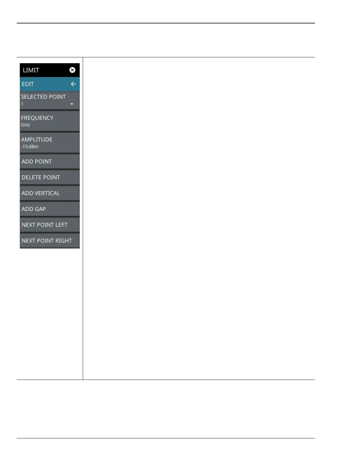
LIMIT EDIT Menu
SELECTED POINT: Displays the limit line point number. Select to select a different point
from the displayed list.
FREQUENCY: Sets the frequency of a limit line inflection point. The frequency of each
point in a limit line can be individually set. When a new point is added, it takes the value
that is halfway between two existing points, or it takes the stop frequency of the current
sweep if no point is higher in frequency than the one being added. See the ADD POINT
button description for more details. Use the keypad or the left and right arrow keys to
change the frequency of an inflection point. The left or right arrows move the inflection
point by ±0.1. Up or down arrows move the inflection point ±1.
AMPLITUDE: Sets the amplitude of a limit line inflection point. The amplitude of each
inflection point can also be individually set. By default, when a new point is added it takes
the amplitude value that is on the limit line at the frequency where the point was added.
Use the keypad (using +/- to set a negative value) or the plus (+) or minus (–) control to
increment the value. The unit of the amplitude limit is the same as the current vertical
amplitude unit (for example, dBm).
ADD POINT: Select this button to add a limit line inflection point. The precise behavior of
this button depends upon which inflection point is active at the time that the button is
pressed. If the active limit point is somewhere in the middle of a multi-segment limit line,
then a new limit point is added that is halfway between the currently active point and the
point immediately to its right. The amplitude of the inflection point will be such that it falls
on the limit line. For example, if a limit point exists at 2.0 GHz with an amplitude of –
30 dBm, and if the next point is 3.0 GHz with an amplitude of –50 dBm, then the added
point will be at 2.5 GHz with an amplitude of –40 dBm. If the last limit point is active
(assuming it is not at the right edge of the display), then the new limit point will be placed
at the right edge of the display at the same amplitude as the point immediately to its left.
Points may not be added beyond the current sweep limits of the instrument. Use the
FREQUENCY and AMPLITUDE buttons to make adjustments to the selected point.
DELETE POINT: Select this button to delete the selected point.
ADD VERTICAL: Select this button to add an inflection point below the currently selected
point.
ADD GAP: Select this button to disconnect the continuous limit line. It can be used when
you don’t want to apply limit to a specific portion of the trace.
NEXT POINT LEFT: Select this button to select the inflection point that is immediately to
the left of the active point, making this newly selected point active for editing or deletion.
With each button press, the active point becomes that point to the left of the previously
active point, until the newly selected active point becomes the left-most point on the
screen.
NEXT POINT RIGHT: Select this button to select the limit point immediately to the right of
the active point, making this newly selected point active for editing or deletion. With each
button press, the active point becomes that point to the right of the previously active point,
until the newly selected active point becomes the right-most point on the screen.
Figure 3-41. LIMIT EDIT Menu