3-12 Setting Up Advanced Measurements Spectrum Analyzer Measurements
3-60 PN: 10580-00447 Rev. H Spectrum Analyzer MG
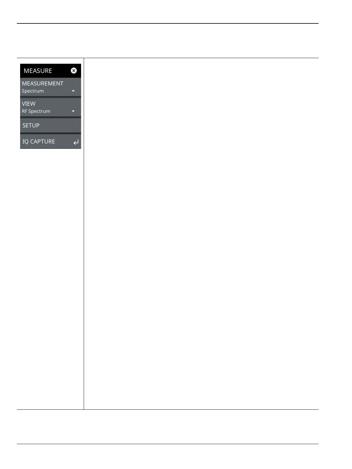
MEASURE Menu
From the main menu select MEASURE > MEASUREMENT menu to select one of the desired measurements.
MEASUREMENT: Select the desired measurement type from the following list:
• Spectrum: Displays the frequency domain spectrum measurement.
•Channel Power: The channel power table and channel lines are added to the
measurement display. Refer to Section 3-13 “Channel Power” on page 3-68.
•OBW: The occupied bandwidth table and channel lines are added to the
measurement display. Refer to Section 3-14 “Occupied Bandwidth” on page 3-71.
• ACP: The ACP table and channel lines are added to the measurement display.
Refer to Section 3-15 “Adjacent Channel Power” on page 3-74.
• SEM: The spectrum emissions mask table and a spectrum mask is added to the
measurement display. Refer to Section 3-16 “Spectrum Emission Mask”
on page 3-77.
• PIM/Interference: Available when Option 24 is installed. The input parameters and
channel measurements tables, max/min level lines, and total channel power signal
indicator are added to the measurement display. Refer to
Section 3-17 “PIM/Interference (Option 24)” on page 3-82.
• EMF Measurement: Available when Option 444 is installed. The EMF
measurement and information tables are added to the measurement display. Refer
to Section 3-18 “Electromagnetic Field (EMF) Measurements (Option 444)”
on page 3-86.
• Coverage Mapping: Available when Option 431 is installed. Coverage mapping
provides signal strength measurements on the instrument display and will plot
color-coded signal values on an interactive map. Refer to Section 3-19 “Coverage
Mapping (Option 431)” on page 3-91.
• AM/FM Audio: Available when Option 24 is installed. The AM/FM Audio provides
audio demodulation capability. Refer to Section 3-20 “AM/FM Audio (Requires
Option 24 or Option 509)” on page 3-103.
Also available when Option 509 is installed. Refer to Section 3-21 “AM/FM
Modulation Measurement (Option 509)” on page 3-106.
•C/I: Carrier-to-Interference is the ratio of power in an RF carrier to the noise power
in the channel. Carrier-to-interference ratio indicates the difference in amplitude
between the desired radio frequency carrier and the noise in a portion of the
spectrum. Refer to Section 3-22 “Carrier-to-Interference” on page 3-112.
VIEW: Selects the desired measurement view from the following list:
•RF Spectrum: RF Spectrum View
• Spectrogram: When Spectrogram view is selected, a Spectrogram view is added
to the display. Spectrogram is only available when the MEASUREMENT is set to
Spectrum.
• All Measurements: This view is only available when AM/FM Modulation
Measurement (Option 509) is installed. The measurement displays audio
spectrum, RF spectrum, audio time domain and audio results.
SETUP: Opens the SETUP menu for the measurement and view selected above, except
for RF SPECTRUM mode. Refer to “SETUP Menu” on page 3-118.
IQ CAPTURE: Opens the “IQ CAPTURE Menu (Option 124/126)” on page 3-63.
Refer to the IQ Capture/Streaming Measurement Guide (10580-00490) for more
information on IQ Capture and Streaming.
Figure 3-46. MEASURE Menu