4-4 Interference Map IA Spectrum Analyzer (Option 24)
4-6 PN: 10580-00447 Rev. H Spectrum Analyzer MG
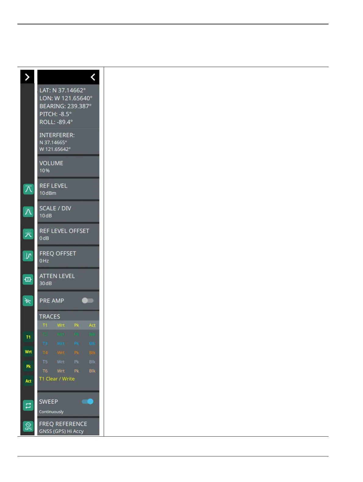
STATUS Panel (Interference Map and Interference Polar)
This Status panel is unique to Interference Map and Interference Polar measurement modes (selected via
MEASURE > MEASUREMENT menu) of IA Spectrum Analyzer.
LAT: Shows the latitude coordinate of the interferer.
LON: Shows the longitude coordinate of the interferer.
BEARING: Direction the MA2700A is pointing (shown in red).
PITCH (vertical level): Indicates the front-to-back orientation.
ROLL (horizontal level): Indicates the side-to-side orientation.
INTERFERER: Shows the GNSS (GPS) coordinates of the interferer.
VOLUME: Sets the audio output volume.
REF LEVEL: Sets the reference level of the top graticule line in the selected units.
If the reference level offset is not zero, OFFSET REF LEVEL is displayed at this
location.
Refer to Section 3-4 “Setting Amplitude Parameters” on page 3-8.
SCALE/DIV: Sets the graticule scale/division for log-based units. This setting does
not apply to linear units.
REF LEVEL OFFSET: Sets the reference level offset in dB units. This setting can
compensate for the presence of external input attenuation or gain.
FREQ OFFSET: Accounts for frequency conversions outside of the analyzer.
Refer to Section 3-3 “Setting Frequency Parameters” on page 3-2.
ATTEN LEVEL: When auto attenuation is off, sets input attenuation.
PRE AMP: Toggles the low-noise front-end preamplifier on or off. Refer to
Section 3-4 “Setting Amplitude Parameters” on page 3-8.
TRACES: Displays the current status of up to six traces or cursors in a quick-view
summary. When the measurement view is set to Spectrum mode trace information
is displayed in this area.
The summary information includes the trace number, type, mode, and detector
type. The active trace will show a highlighted background with the mode and
detector type restated under the table. Selecting a trace in the summary panel
activates the pressed trace or cursor and opens the TRACE menu, allowing you to
select and set up an individual trace or cursor as desired. Refer to
Section 3-7 “Setting Trace Parameters” on page 3-21.
SWEEP: Toggles the current sweep setting between continuously or sweep once.
Refer to Section 3-8 “Setting Sweep Parameters” on page 3-38.
FREQ REFERENCE: Indicates the current frequency reference source of Internal
High Accuracy (used after GPS has lost sync, but while the internal clock still has
good GPS reference), Internal Standard Accuracy, External, or GNSS (GPS) Hi
Accy (requires GPS). The instrument automatically selects the frequency reference
in the following order of priority: external, GPS, then the internal time base.
Figure 4-5. Status Panel with Mini Status Panel Icons (Interference Map)