5.6 Measuring Laser Diode Modules
5-43
5
5.6.3 Calculation Method
1. The peak level of waveform is detected.
2. The side mode wavelength and level are measured in accordance
with the Search Resolution.
3. SMSR is measured in accordance with the SMSR Parameter.
4. Mode Offset, Stop Band, Center Offset are calculated.
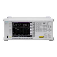
Processing is performed as follows where the wavelength of the
maximum peak is λ
max
, the wavelengths on both sides of the
maximum peak are λ
left
and λ
right
, and the side mode wavelength is
λ
side
.
Mode Offset = λ
side
– λ
max
Stop Band = λ
right
– λ
left
Center Offset =
However, λ
side
is the side mode selected at Side Mode 2nd Peak, Left,
or Right.
Figure 5.6.3-1 Position of Peak Wavelength and Side Modes
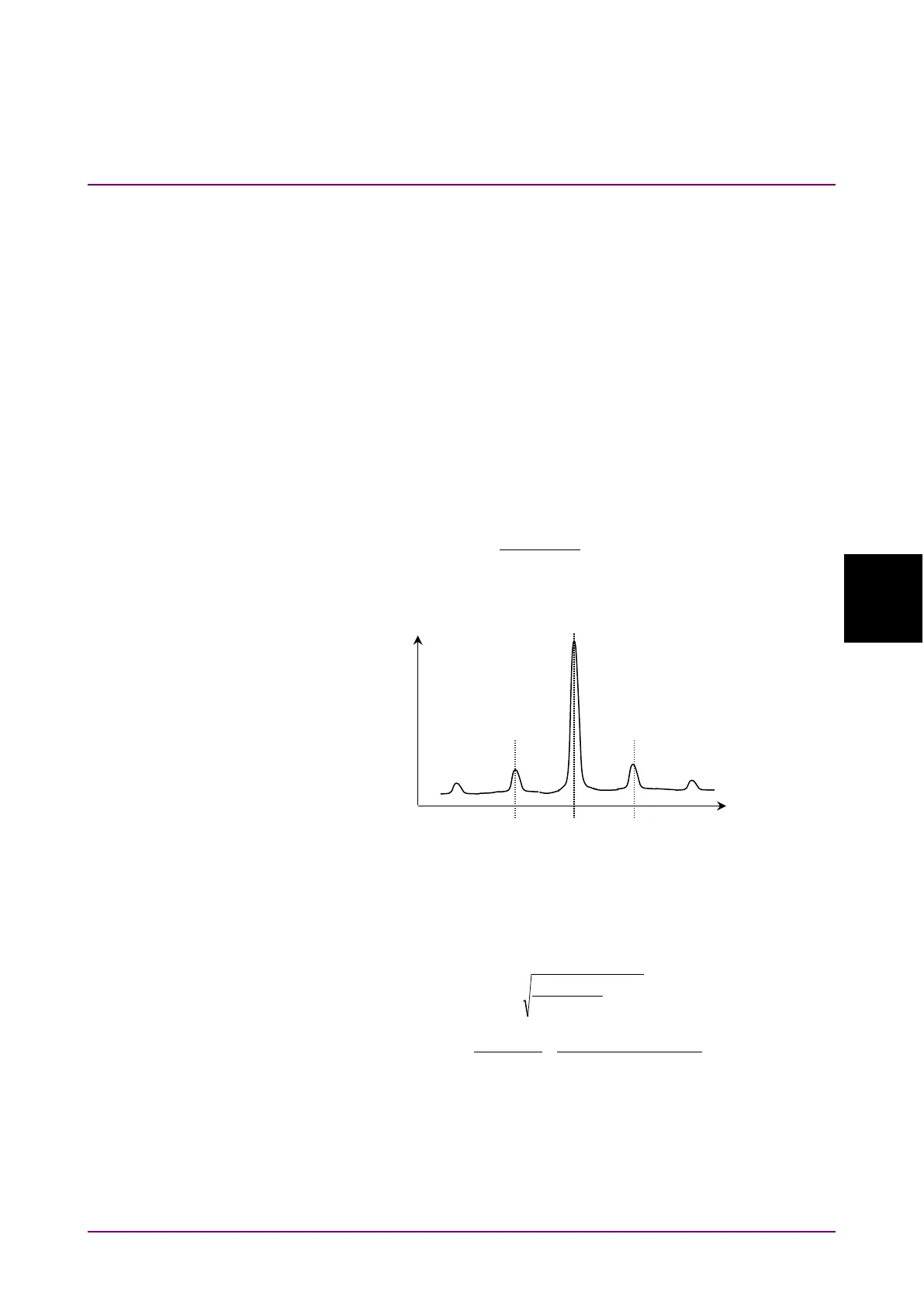
5. σ is calculated as follows where B
n
and λ
n
(n = 1, 2, 3 ….i) is measured
level and wavelength at the point with a level more than a slice level
down from the peak.
BiBB
iBiBB
Bn
nBn
c
+・・・+
λ+・・・λ+λ
=
λ
=λ
21
22
11
∑
∑
×
6. Spectrum width is calculated in accordance with the Kσ.
7. The Signal wavelength is measured in accordance with the
Wavelength-Detection Type setting of Signal Parameter.
8. The Signal level is measured in accordance with the Level-Detection
Type of Signal Parameter.
left
Max
right