5.8 Measuring Optical Amplifier (Wavelength Division Multiplex)
5-67
5
5.8 Measuring Optical Amplifier (Wavelength Division
Multiplex)
With the optical amplifier (WDM), the following items are measured
simultaneously for the multiple optical signals.
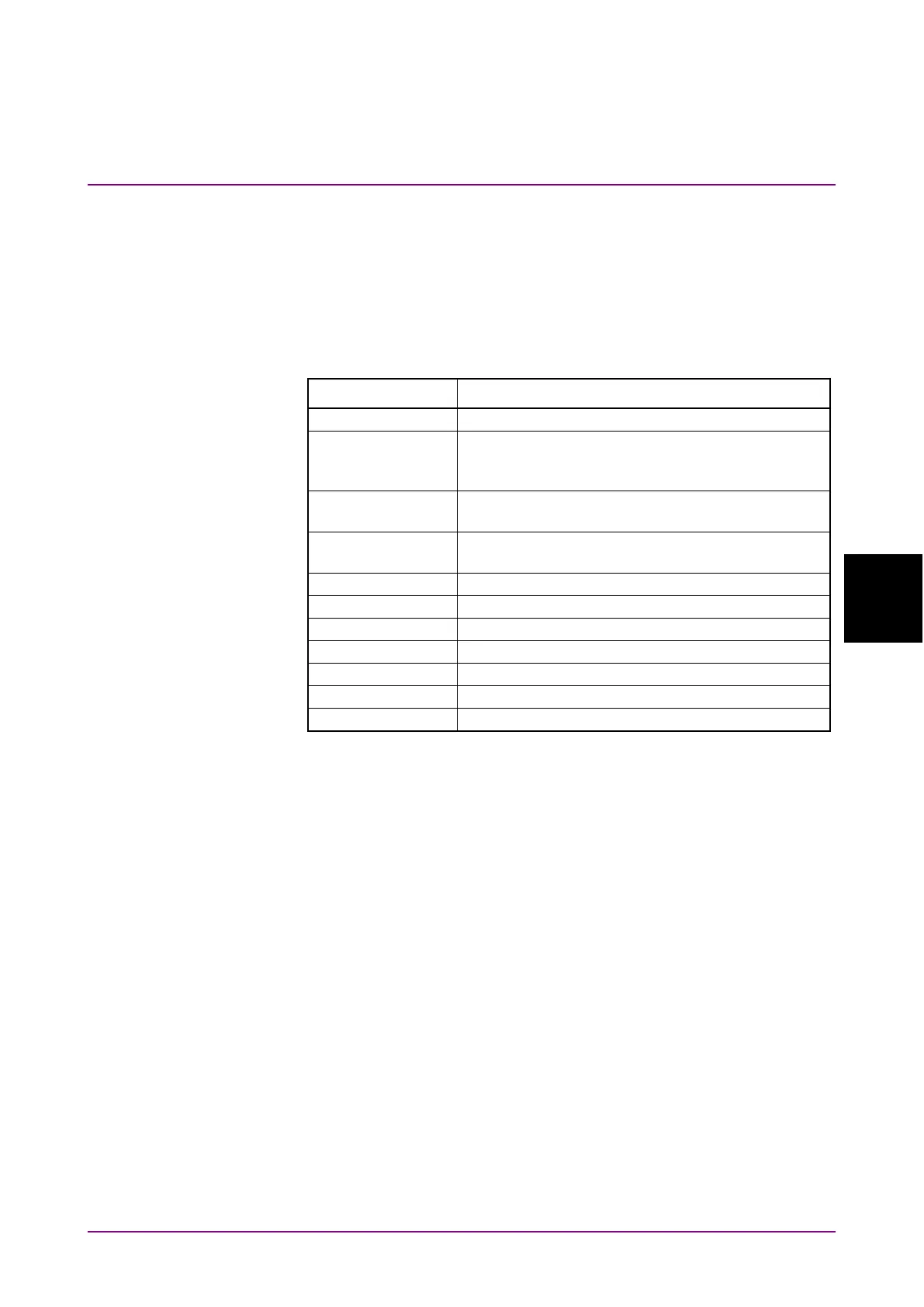
Table 5.8-1 Opt. Amp Multi Measurement Items
Screen Display Description
Slope when a straight line approximation is
performed based on the gain obtained for each
Ratio between the maximum gain and the
minimum gain
Number of signal (sequential number added from
short wavelength)
Optical signal level input
Optical signal level output
The noise figure and gain are calculated from the power of the optical
input to the optical amplifier (Pin), the power of the optical signal output
from the optical amplifier (Pout), and the ASE level.
Refer to 5.8.4 “Calculation Method” for details.
Pin, Pout, and ASE are measured from the optical input to the optical
amplifier and the spectrum of the optical output of the optical amplifier.