5.4 Measuring PMD (Polarization Mode Dispersion)
5-15
5
5.4.2 Calculation Method
The differential group delay Δτ is calculated using the following equation.
)12(
21
)1(
ll
ll
τ
−×
×
×−×=∆
c
nk
k: Mode coupling factor
c: Light Velocity 2.99792458 × 10
8
m/s
n: Peak Count
λ1: 1st Peak Marker wavelength
λ2: Last Peak Marker wavelength
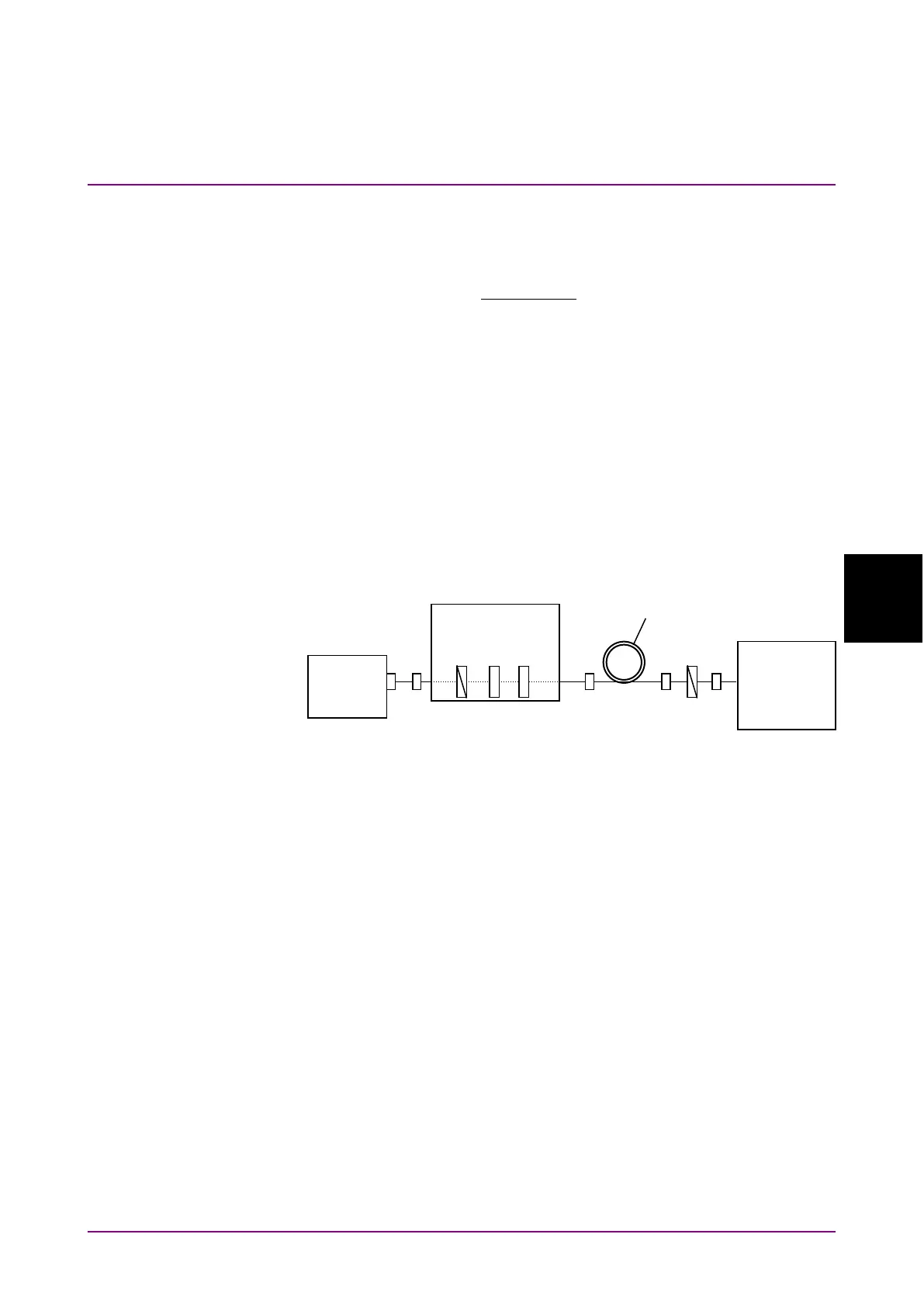
The measurement system is shown in the following diagram. A SLD
(Super Luminescent Diode) light source or an ASE (Amplified
Spontaneous Emission) light source can be used as the wideband light
source.
Figure 5.4.2-1 PMD Measurement System
5.4.3 Procedures
To display polarization mode measurement
1. When the name of the
F7
horizontal key is not
Application
, press
F8
,
and then press
F7
.
2. Press
f4 PMD Test
to display the measurement result display field.
To calculate automatically
1. Press
f1 Auto/Manual
and select Auto.
2. Input the optical signal.
3. Set the wavelength, resolution, and level scale.
4. Press
Repeat
.
5. Adjust the polarization controller to maximize the difference between
the measured spectrum maximum and minimum values.
6. Press
f2 Mode Cpl Factor
and input the mode coupling factor in the
range 0.01 to 1.00.
P: Polarizer
Q: 1/4 Wavelength
board
light
DUT
(Optical fiber cable, etc)
controller
P
Q
H
MS9740B
Optical
Spectrum