Chapter 5 Measurement Functions
5-94
5.9.4 Procedures
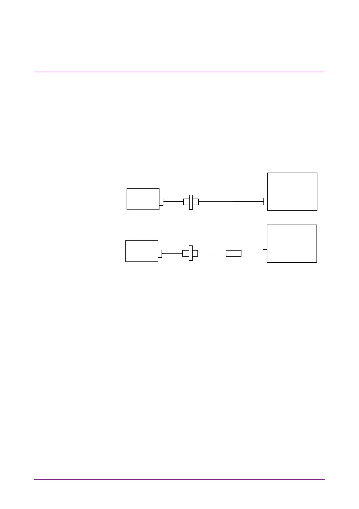
In this example, Trace A is used to measure the spectrum of the light
source, and Trace B is used to measure the spectrum of the light passed
through the WDM filter. The waveform obtained by subtracting Trace A
from Trace B is saved as Trace C. The WDM filter analysis is performed
on the waveform of Trace C.
When measuring the WDM filter, use a light source having a broadband
spectrum and a good level stability.
Figure 5.9.4-1 Measuring System for the WDM Filter
To obtain the waveform data of the WDM filter
1. Power on the light source and warm it up until the level stabilizes.
2. Connect two optical fiber cords and an optical adapter, as shown in
Figure 5.9.4-1 (a).
3. Press
F6 Trace
,
f1 Active Trace
, and
f1 A
, in this order, and Trace A
becomes the active trace.
4. Set the wavelength, resolution, and level scale.
5. Press
Single
or
Repeat
. The data is saved to Trace A.
6. Press
F6 Trace
,
f2 Trace Type
and
f2 Fix
, in this order.
7. Connect the WDM filter as shown in Figure 5.9.4-1 (b).
8. Press
f1 Active Trace
and
f2 B
, in this order, and Trace B becomes
the active trace.
9. Press
Single
or
Repeat
. The data is saved to Trace B.
10. Press
f1 Active Trace
and
f3 C
, in this order, and Trace C becomes
the active trace.
11. Press
F6 Trace
,
f2 Trace Type
, and
f3 Calculate
, in this order.
12. Press
F6 Trace
and
f4 Calculation
, in this order.
(a) Light Source Measurement
Optical Spectrum
Analyzer
(b) Measurement of Light Passed Through WDM Filter
Optical Spectrum
Analyzer
Source
Source